4 Parts Replacement VJ-1604 Maintenance Manual
Rev.-05 4-46
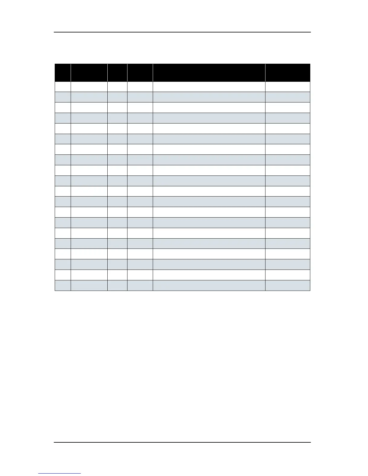
2. Detach the connectors listed below from the heater relay board.
Table 4-2 Connectors to Heater Relay Board
No. Connector
No.
# of
Pins
Color Connect to Remark
1 J1 2 White EX-AC-OUT [HEATER CONT (J23)]
2 J2 4 White Plt_Heat 1
3 J3 40 Black HEATER CONT (J6) FFC
4 J4 2 White Not in use
5 J5 4 White Plt_Heat 2
6 J6 2 White Inlet (Large)
7J7 2 White Pre_Heat
8 J8 2 White Pre_Heat
9J9 4 White Aft_Heat
10 J10 2 Blue Cooling FAN
11 J11 4 White Vacum FAN (#1, #2)
12 J12 2 White Platen_Thrm 1
13 J13 2 Black Platen_Thrm 2
14 J14 4 Black Vacum FAN (#3, #4)
15 J15 2 Red Pre_Thrm 1
16 J16 2 Yellow Pre_Thrm 2
17 J17 3 White Aft_Thrm 1
18 J18 3 Black Aft_Thrm 2
19 J19 3 Red Reserve 1 Thrm
20 J20 3 Yellow Reserve 2 Thrm