Engine System - LPG 158Service Manual – CS7000
Circuit Descriptions
Ignition System
The ignition system consists of a spark control module (aka Ignitor), three ignition coils, and a crank position
sensor. The crank position sensor reads a rotating 6 toothed ring which is mounted on the ywheel between
the ywheel and the engine.
The heart of the system is the spark control module. It controls the current ow of each ignition coil primary
circuit in order to control when spark occurs based on inputs from the crank position sensor. Each coil res
twice per cylinder cycle. Once to initiate the power stroke and once in exhaust stroke (waste spark)
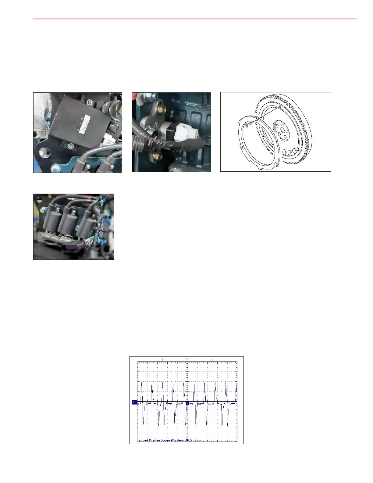
The crank sensor is a two wire “ AC pulse generator”. It has a wire coil inside of it. As the toothed ring
rotates, the teeth pass in line with the end of the sensor tip. This induces a voltage spike that the spark
control module can “read” as cylinder position information. The number of spikes per minute is translated as
engine RPM. One tooth on the ring is wider than the other ve. This creates a unique “spike” so that the
spark control module can distinguish the cylinders from one another. This allows it to re the right ignition
coil at the right time. Below is what the crank sensor wave form looks like on an oscilloscope. Notice that
every sixth pattern is “wide”.
Crank Position Sensor
Spark Control module
Toothed Ring and ywheel
Ignition Coils
WaveStar : Cougar Crank Sensor Waveform Page: 1

 Loading...


