Wheel System, Traction 433Service Manual – CS7000
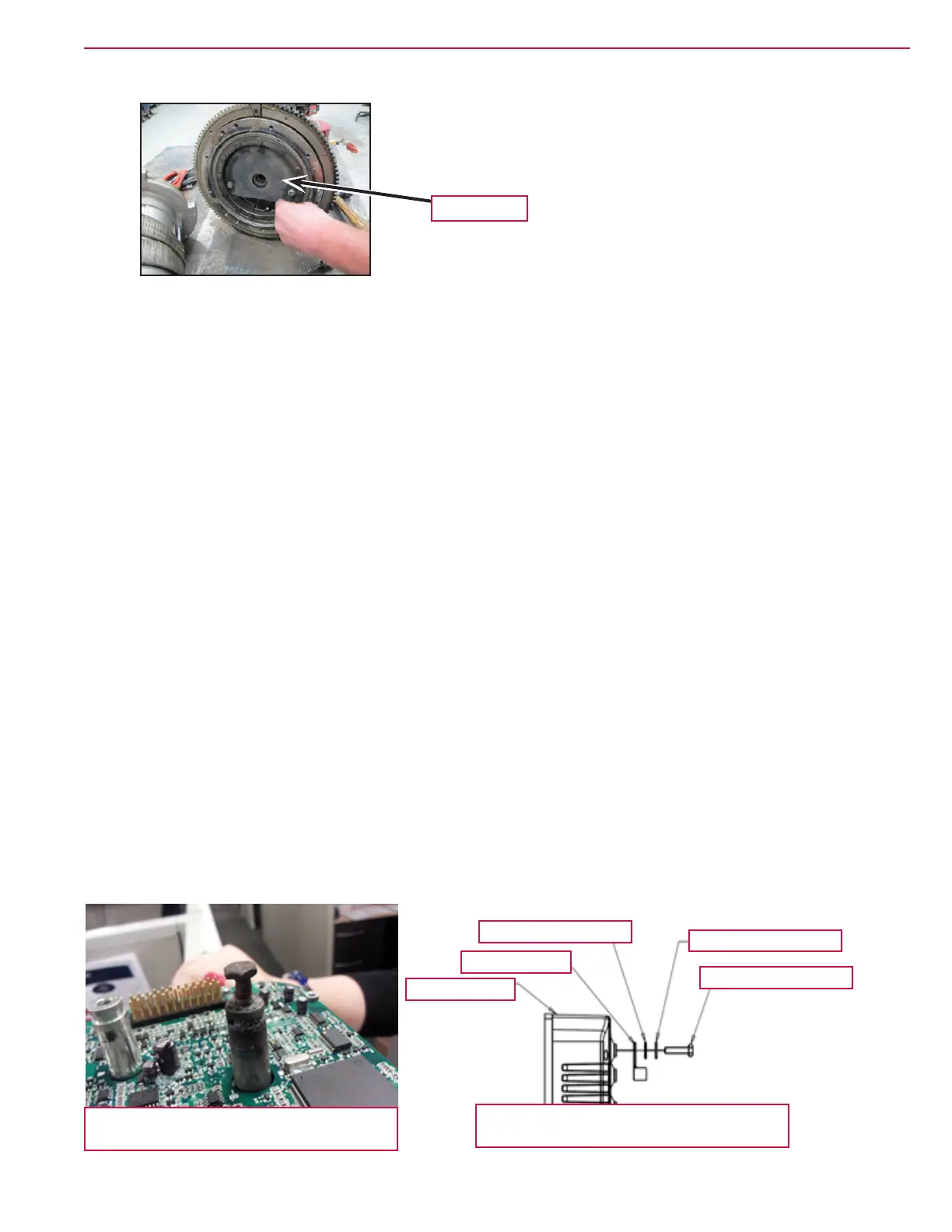
c. If installing a new gear box, be sure to transfer the splash shield.
d. Apply 56510412 (OPEN GEAR LUBE) to front 180° of ring gear teeth and all around pinion gear
teeth.
19. Reassemble in reverse order.
Drive Wheel
1. Block front wheels
2. Loosen drive wheel lug nuts.
3. Jack the rear of the machine up to get the drive wheel off the ground.
4. Remove the drive wheel lug nuts and remove the wheel.
5. Reassemble in reverse order.
Drive Controller
1. Disconnect the main power connector.
2. Remove the recovery tank.
3. Label the power and motor cables to aid in correct reassembly.
4. Remove the bolts securing the motor and power cables.
5. Disconnect the low current connector.
6. Remove controller attaching screws and remove the controller.
7. Reassemble in reverse order. When attaching cables use the correct hardware in the correct order to
avoid damage caused from a loose connection. Torque to 90 IN-LBS (10.17 Nm).
Damaged Drive Controller terminal from loose
connection. (Case removed for clarity)
Drive Controller Cable Hardware Order
WSH, INT SHPRF 1/4
SCR-HEX M6-1 X 25mm
WSH, FLT SAE 1/4
Cable Terminal
Drive Controller
Splash shield