Control System 81Service Manual – CS7000
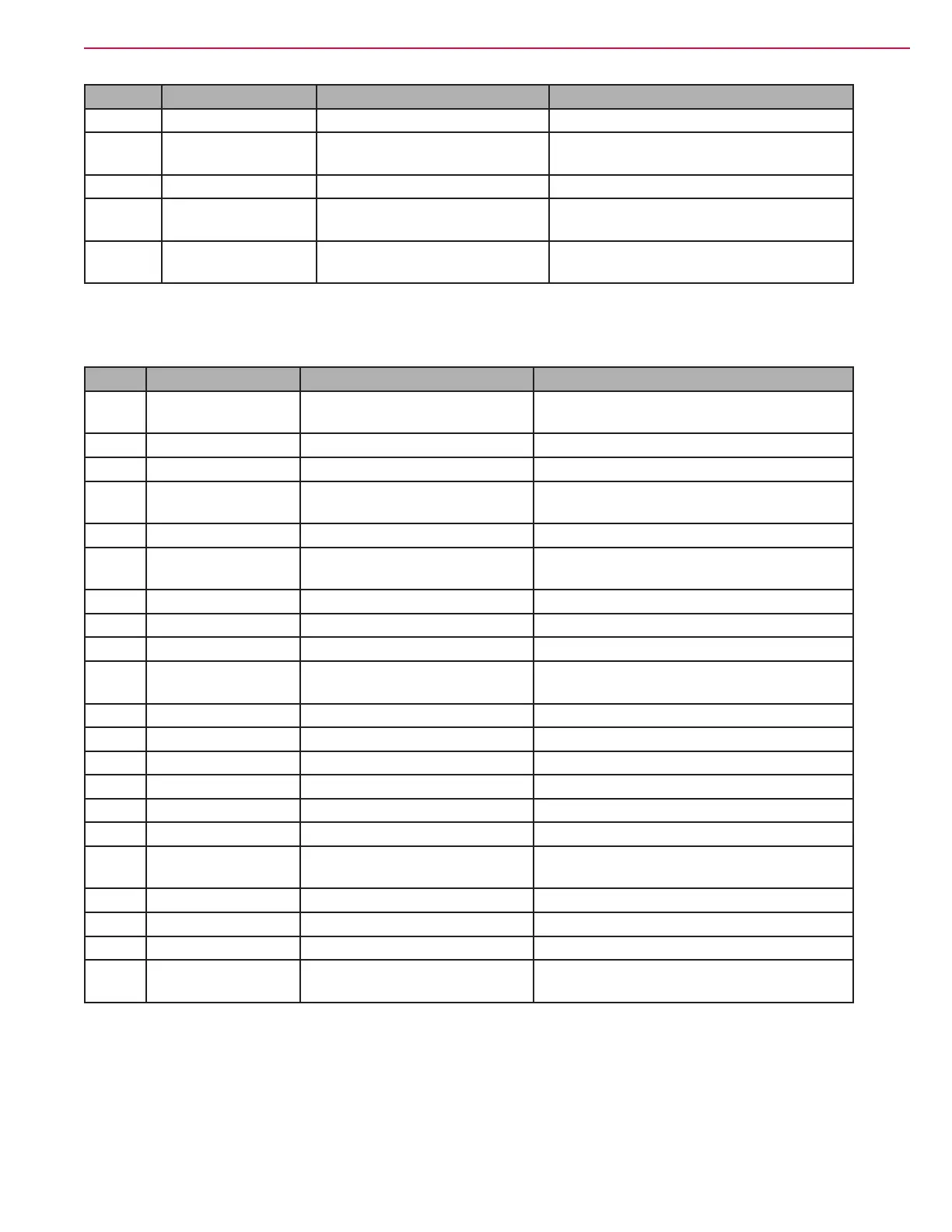
J3 Pin Wire Circuit Description Value/Condition
31 ---
32 049 ORN/BLK Glow Plug Output 12v out to
energize relay
11.6v when glow plug relay energized 0v
key off or after time out period
33 ---
34 056 GRA/BLK VACC3a Power supply from
Aux Contactor
0v Key Off 37v Key On (Aux Relay
energized)
35 055 GRA/BLK VACC3b Power supply from
Aux Contactor
0v Key Off 37v Key On (Aux Relay
energized)
J7 Connector (Black)
J7 Pin Wire Circuit Description Value/Condition
1 092 GRN/BLU Interlock Switch Input 37v when all interlock switches closed 0v
otherwise
2 095 GRN CAN Bus Low 2.448v
3 099 YEL CAN Bus High 2.52v
4 102 GRA Run Signal Output 14v when engine running 0v key off, on or
cranking (starter disabled)
5 108 GRA/YEL Engine Coolant Temperature 4.99v normal temp
6 112 TAN/WHT Fuel Level Sender 3.3v open circuit 1.8v oat at bottom 0.37v
oat at top
7 117 YEL/RED Low LP Pressure Switch 5.0v when open
8 ---
9 ---
10 130 WHT/BRN +12v Power out to Control
Panel
12.07v
11 133 BLK B- (Ground) for Control Panel 0.002v
12 050 YEL/BRN Suppression Diode 37v key on
13 141 ORN Key Switch On Input 37v key on 0v key off
14 046 RED/BLK Hopper Interlock Switch 0.0v full down position 4.8v otherwise
15 035 GRA/YEL Extended Scrub Level Switch 4.8v (machine not equipped)
16 143 WHT/GRA Dust Control Filter Switch 4.8v (machine not equipped)
17 145 ORN/GRA Brake Switch 0v brake pedal at rest position 4.8v brake
pedal pressed (not at rest)
18 151 YEL/VIO
19 155 VIO/GRN Key Switch Start Input 37v key in start 0v key off or on
20 ---
21 161 RED/ORN Scrub Deck Retract Limit
Switch
0.0v full up position 4.8v otherwise

 Loading...


