Squeegee System 351Service Manual – CS7000
Removal and Installation
Warning! Before removing or reinstalling any machine components, make sure the key switch
is off, the key is removed from the machine and the parking brake is engaged.
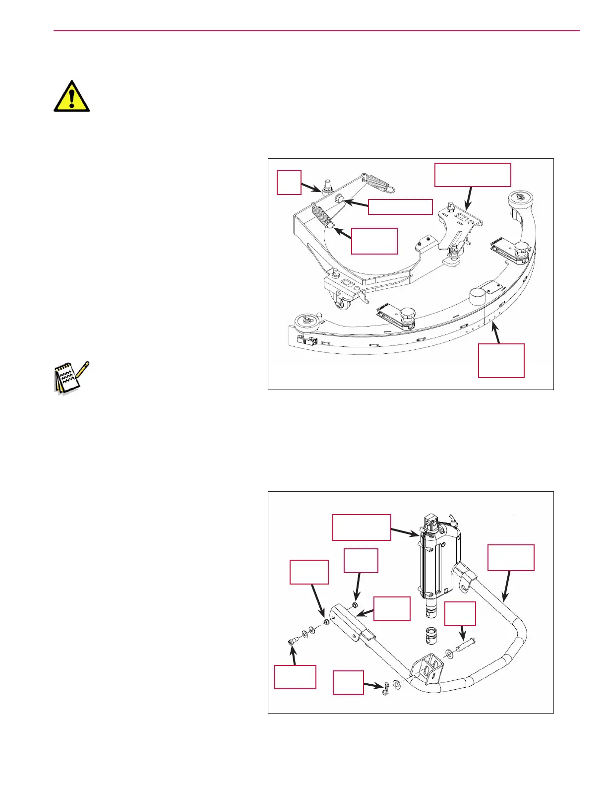
To Remove and Reinstall the Squeegee Support Assembly
1. Remove the Rear Squeegee Assembly.
2. Disconnect the Extension Springs from
the Squeegee Support Assembly using
a spring puller. (See the Special Tools
section.)
3. Remove the 3/4”-16 Screw holding the
Squeegee Support Assembly to the Rod
End
.
4. Carefully remove the Squeegee
Support Assembly
from the machine.
5. Reinstall the Squeegee Support
Assembly
by following the above steps
in reverse order.
Note: Use removable Loctite®
thread sealer when
reinstalling the 3/4”-16
Screw
. Tighten the 3/4”-16
Screw
to 270 ft/lbs.
To Remove and Reinstall the Squeegee Lift Arm
1. Remove the Rear Squeegee Assembly and Squeegee Support Assembly.
2. Disconnect the Extension Springs from
the Squeegee Lift Arm.
3. Remove the Cotter Pin, washers and
Clevis Pin connecting the Squeegee Lift
Actuator
to the Squeegee Lift Arm.
4. Remove the Shoulder Screws, at
washers, Flange Bearings and Nyloc®
Nuts
connecting the Front Brackets to
the machine frame, then remove the
Squeegee Lift Arm from the machine.
5. Reinstall the Squeegee Lift Arm by
following the above steps in reverse
order.
Rear
Squeegee
Assembly
3/4”-16 Screw
Extension
Spring (2)
Rod
End
Squeegee Support
Assembly
Shoulder
Screw
Flange
Bearing
Nyloc®
Nut
Front
Bracket
Cotter
Pin
Clevis
Pin
Squeegee
Lift Arm
Squeegee Lift
Actuator

 Loading...


