Solution System 321Service Manual – CS7000
GRA VIO/ORN
Fuse, 400 A
Contactor, Aux
S14
Ignition Switch
VACC3
CB3
25 Amp
1
13
B1
B
3
2
122
A1 Main Machine Controller
A3 Control Panel
CAN
BUS
J3-34 Input
Vacc 3a
J7-19 Start Input
J7-1 Interlock
Input
J7-15 Input
42V Alternator
J2-14 Output
J7-12 Supression
Diode
J3-35 Input
Vacc 3b
J3-1 PWM Output
J3-24 Output
J3-2 PWM Output
RED
BLU/GRN
VIO/GRN
BLU/GRNGRA
RED
GRA/BLK
GRA/BLK
RED BLK
BLK
J3-15
Ground
Pump - Extended Scrub
M25
F1
K9 Aux Contactor
Battery
36V
YEL/BRN BLK/ORN
ORN
ORN GRA/ORN
ORN
M
GRA
GRN/WHT
Pump - Low Pressure (optional)
M23
M
GRA
VIO
RED/YEL
WHT/BRN
BLK
YEL
GRN
GRN/YEL
Chassis
Ground
Pump - Solution Control (optional)
M19
M
J2-7 PWM Output B
WHT/BRN
WHT/YEL
J2-19 PWM Output A
Pump - Chemical Metering (optional)
M17
M
J2-20 PWM Output
VIO
YEL/ORN
Solution Valve
L1
J7-14
Input
BLK
J3-16
BLK
J3-18
BLK
J3-19
BLK
J3-20
BLK
J3-21
BLK
WHT/ORN
J3-29
J3-9 Output
High-pressure
Pump Clutch
J7-10 +12V
J7-11 B-
J7-3 CAN H
J7-2 CAN L
+
+
-
VACC2
CB2
K9
25 Amp
21
12
YEL/BRN
J7-13 Key
Switch Input
VIO
VACC1
CB1
25 Amp
21
B-
G
ORN
Safety Switch
Relay (signal from
A5 Steer by
Wire Controller)
621 22114
PINK TAN GRN/BLU
K14
Seat Switch
S9
Emergency
Stop Switch
S15
Fe
S13
Battery
Interlock
J1-4
J1-3
J1-2
J1-1
Extended Scrub
Level Switch
(closes when
tank is empty)
21
RED/BLK
GRA/YEL
BLK
BLK
S3
Hopper
Interlock Switch
Fe
2
1
S4
J2-21 PWM Output B
WHT/BRN
WHT/YEL
J2-32 PWM Output A
Pump - Chemical Metering (optional)
M18
M
43
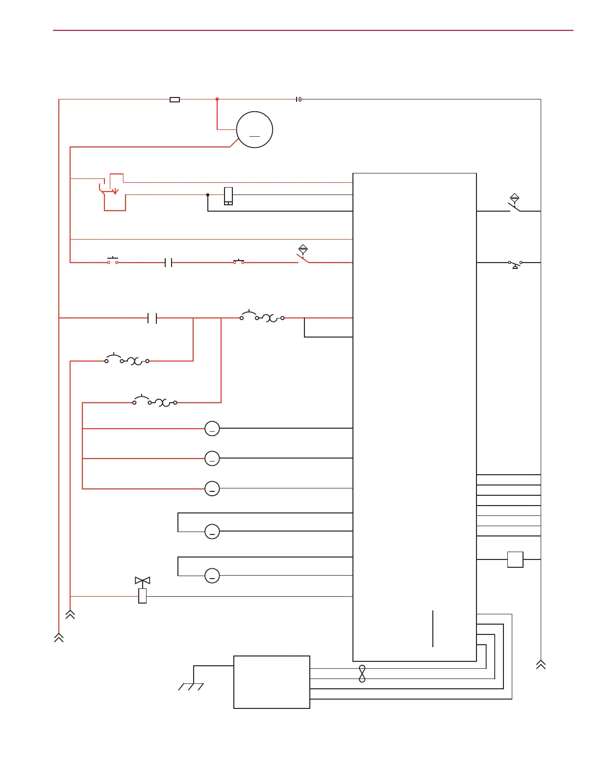
Solution System Wiring Diagram
 Loading...


