225Service Manual – CS7000
Engine System, Diesel
This chapter covers the fuel supply system, engine RPM governor control system and glow plug starting aid.
See the Kubota D1305 Workshop Manual 9Y111-00124.pdf for information related to the mechanical engine
and high pressure fuel injection system.
Functional Description
One of the engines available in the CS7000 is a Kubota Diesel (D1305-E3B-KEA-1). It is a three cylinder,
liquid cooled, naturally aspirated engine. It has mechanical injector pump that is tted with an actuator
which physically moves the fuel lever inside the pump.
Fuel is stored in a tank on the right side of the engine compartment. The tank swings out to provide easier
access to the engine compartment and contains a fuel level sending unit. An electric pump supplies low
pressure fuel to the diesel injector pump. There is a replaceable fuel lter cartridge between the fuel pump
and the injector pump. The injector pump has s small “return” line that runs to the closest injector. The
return circuit is carried from injector to injector where it exits the rear injector and is connected to a hose
which returns back to the fuel tank. .
The engine uses glow plugs to aid in starting a cold engine. The main machine controller operates a glow
plug relay which supplies power to the glow plugs when needed.
The engine RPM is controlled with the Woodward APECS 3000 Electronic Engine Speed Governing System
based on requests from the main machine controller. The main machine controller sends signals to the
Woodward Gov. controller to request one of three engine speeds based on operator request or cleaning mode.
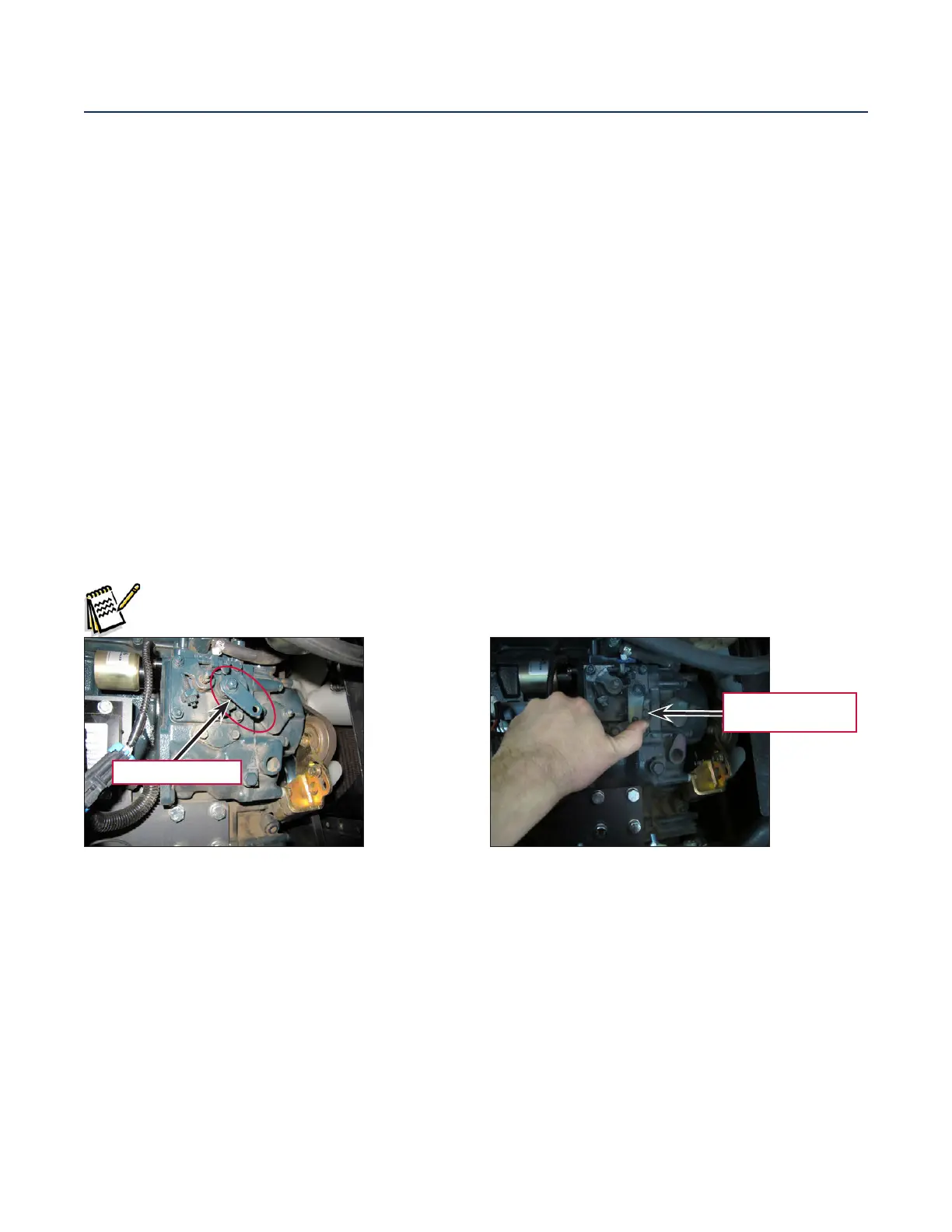
Note: There is a “dead man” level on the side of the injector pump that can be used to shut the
injection pump fuel down to shut off the engine manually.
The cooling system consists of a standard radiator and belt driven fan. Note that the fan pushes air away
from the engine and out through the radiator.
Engine starter control
To get the engine starter to engage, the key switch is held in the start position which supplies 36 volts to the
main machine controller connector J7 pin 19. This is the start input request. The main machine controller
receives a 12 V supply on connector J3 pin 23 from the engine starter battery. It uses this voltage supply to
send voltage out connector J3 pin 10 to the starter solenoid.
Dead Man Lever
Move to shut
down engine
Dead man lever held in shut down position
Dead man lever in normal run position

 Loading...


