Hopper System 252Service Manual – CS7000
Hopper Hydraulic System Circuit Details
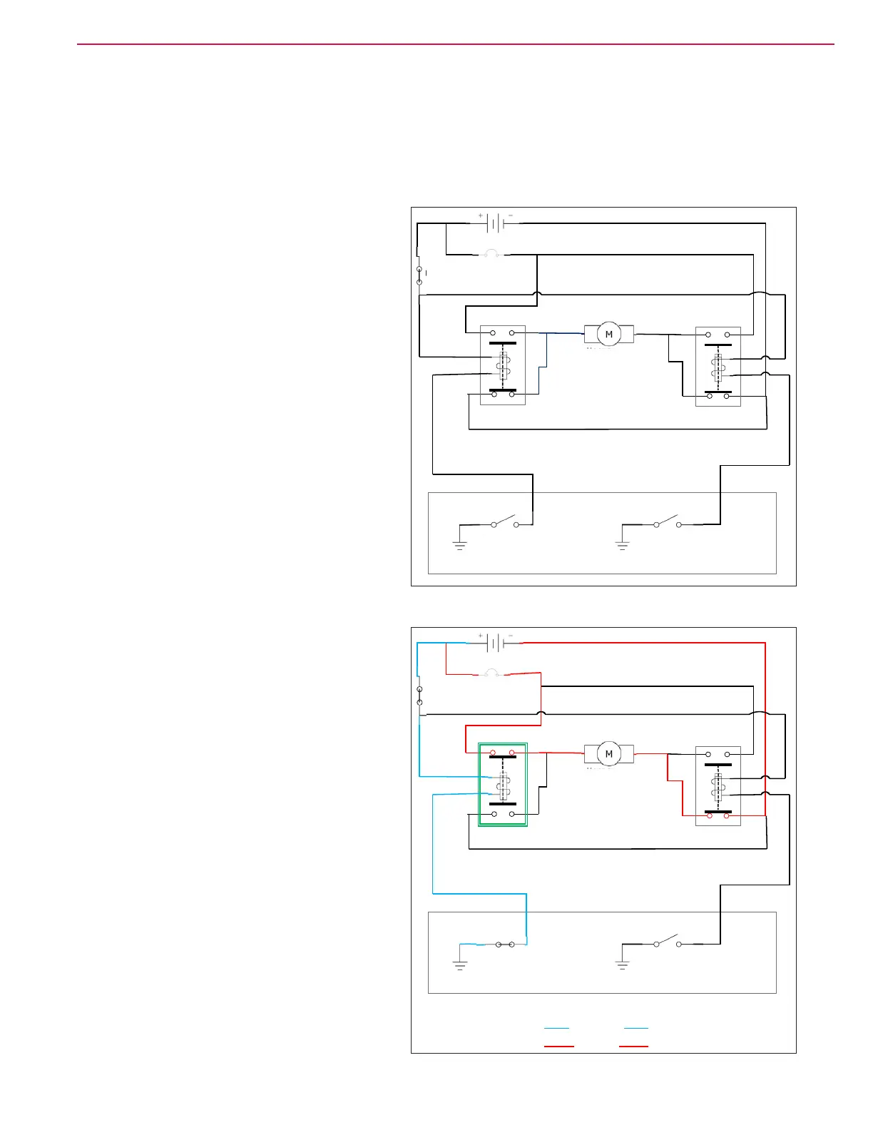
A hydraulic cylinder (ram), driven by a self-contained hydraulic pump and motor, raises and lowers the
hopper. The pump motor power and ground polarity are reversed to make the motor run in opposite
directions. Two contactors (K11 and K12) are used to operate the pump. Each contactor has two sets of
contacts; one that is closed when at rest (normally closed) and one that is open (normally open) when at rest.
Hopper at Rest
When the hopper is “at rest”, the normally-
closed contacts of each contactor connect both
sides of the hopper hydraulic pump motor to
battery negative. Since there is no difference
in electrical pressure (voltage) across the
pump, no current ows and the pump remains
“Off”.
Hopper Being Raised
When the operator pushes the button to raise
the hopper, the main machine controller
energizes the K11 contactor by grounding the
control winding of the contactor. This causes
a magnetic eld to pull the normally-closed
contacts open, and at the same time closes
the normally-open contacts. Battery voltage
is now applied through the closed set of K11
contacts to one side of the pump. The other
side of the pump is connected to battery
negative through the normally-closed contacts
of the K12 contactor. This completes the
circuit and causes the pump to run in the “Up”
direction.
K11
At rest
K12
At rest
Hopper
Hydraulic
Pump Motor
Key switch
Main Machine Controller
K11
Energized
K12
At rest
Hopper
Hydraulic
Pump Motor
Key switch
Main Machine Controller
Control Circuit
Load Circuit
Hopper UP

 Loading...


