Solution System 328Service Manual – CS7000
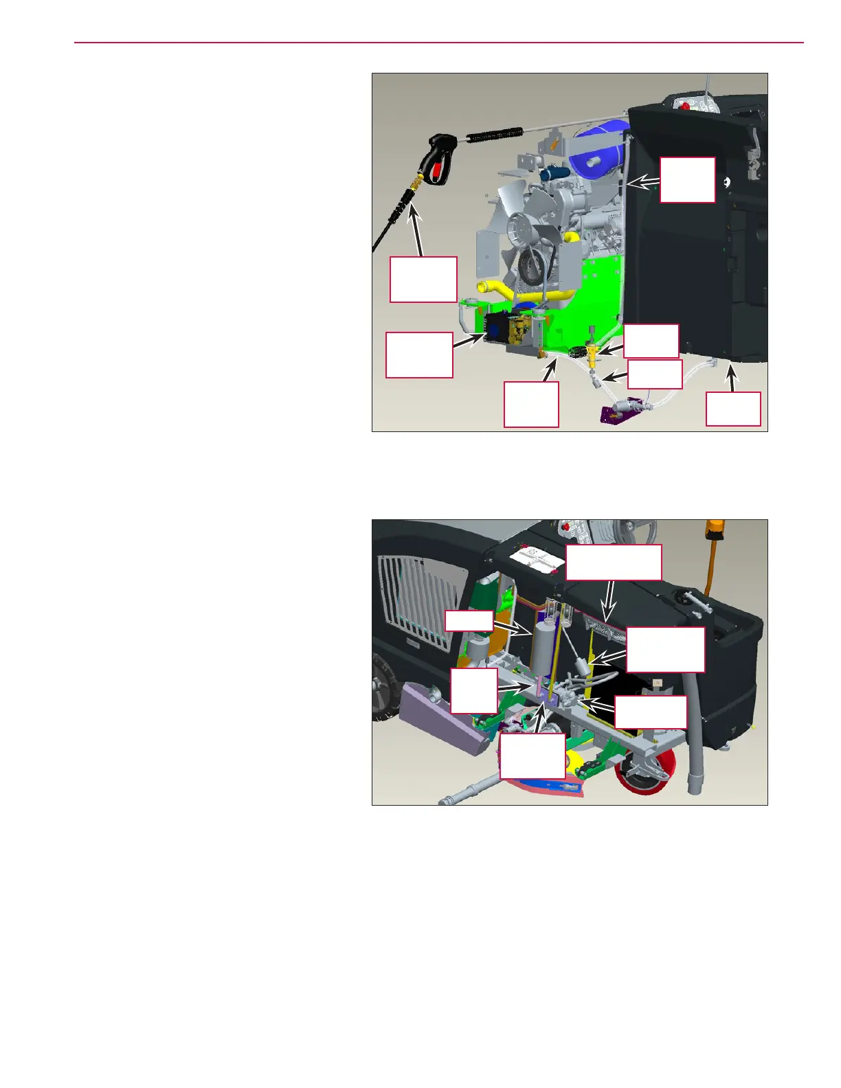
The Solution Supply Line supplies solution
from the Solution Tank to the High-pressure
Pump
. The High-pressure Pump pumps the
solution to the Relief Valve which functions
as follows:
• If the trigger valve on the High-pressure
Wand
is open, the solution ows through
the Hose Coupler and to the attached
High-pressure Wand.
• If the trigger valve on the High-pressure
Wand
is closed, the Relief Valve directs the
solution into the Solution Return Line and
back into the Solution Tank.
Note that the Relief Valve is pre-set at the
factory and is not adjustable.
Extended Scrub System
When the Extended Scrub Level (oat) Switch
inside the Recovery Tank closes to indicate
adequate water level, the Extended Scrub
Pump
switches on to pump water to the
scrub brushes. The water passes through
the Strainer inside the Recovery Tank,
then through the Water Supply Line in the
Bulkhead Plates and Gasket to the inlet side
of the Extended Scrub Pump. Note that the
second piece of conduit in the Bulkhead Plates
and Gasket
is for the Extended Scrub Level
Switch wires.
The Extended Scrub Pump is mounted to a
bracket outside of the Recovery Tank. The
water from the Extended Scrub Pump is
plumbed into the solution line upstream of
the solution solenoid valve.
High-
pressure
Wand
Solution
Return
Line
High-
pressure
Pump
Solution
Supply
Line
Relief
Valve
Hose
Coupler
Solution
Tank
Strainer
Water
Supply
Line
Extended
Scrub Level
(oat) Switch
Extended
Scrub Pump
Bulkhead
Plates and
Gasket
Recovery Tank
(inside view)
 Loading...


