Steering System 358Service Manual – CS7000
Circuit Description
The steering controller power has more than one power supply. The main heavy current power sources are
bolt on lugs that supply both battery positive and negative connections. These connection points are clearly
labeled on the controller. This power is used to convert the direct current to 3 phase alternating current,
which drives the actuator motor. There is also a switched power source that goes to J5-1. This power begins
at the battery positive terminal goes through circuit breaker #4, through the ignition switch, through the
seat switch and then to connector J5 pin 1. This is used to “wake up” the controller and supply power for
lower current circuits. Power is also supplied to J5 pin 12 but this is not truly a power supply. It is used to
identify what machine the controller is attached to.
The steering controller sends a 5 volt power supply out of J5-3 which provides power to the steering actuator
encoder at pin 1 and the steering wheel rotation sensor encoder pins 4 and 8. The steering rotation sensor
encoder has 2 grounds at pins 3 and 7. These are not connected directly to battery negative but go to steering
controller J5-4. The controller provides a “clean ltered ground” for the encoder circuits. The encoder built
into the steering actuator also has a ground at pin 6 which is grounded through the controller J5-4.
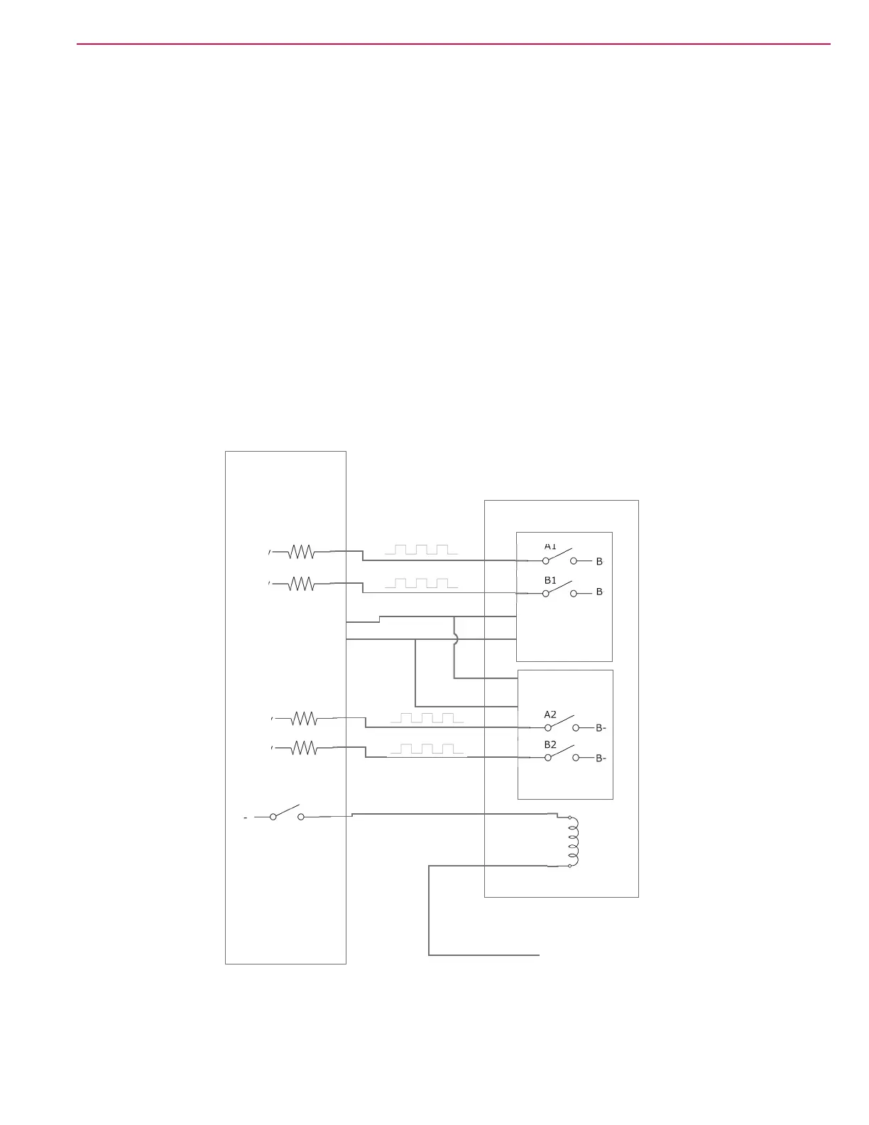
The steering wheel rotation sensor encoder has 4 “internal switches” (See image below) Each switch is fed
approximately 5 volts (4.7v) from the steering controller on its own wire. As the steering wheel rotates, the
switches cycle on and off to ground causing the 5v to drop to 0v and back up again. This creates four
separate 5 volt square wave signals which, are “read” by the steering controller. Note that the encoder
circuits use “twisted pair” wiring to eliminate electrical noise.
+5v
B-
B-
B-
B-
B-
+4.7v
+4.7v
+4.7v
+4.7v
Steering Controller
Steering Wheel Rotation Sensor
Encoder 2
Encoder 1
B-
+36v
TFD Winding
A1
A2
B1
B2

 Loading...


