Steering System 359Service Manual – CS7000
As the steering wheel rotates, the A1 signal switches back and forth from 0v (low) to 5v (high). When viewed
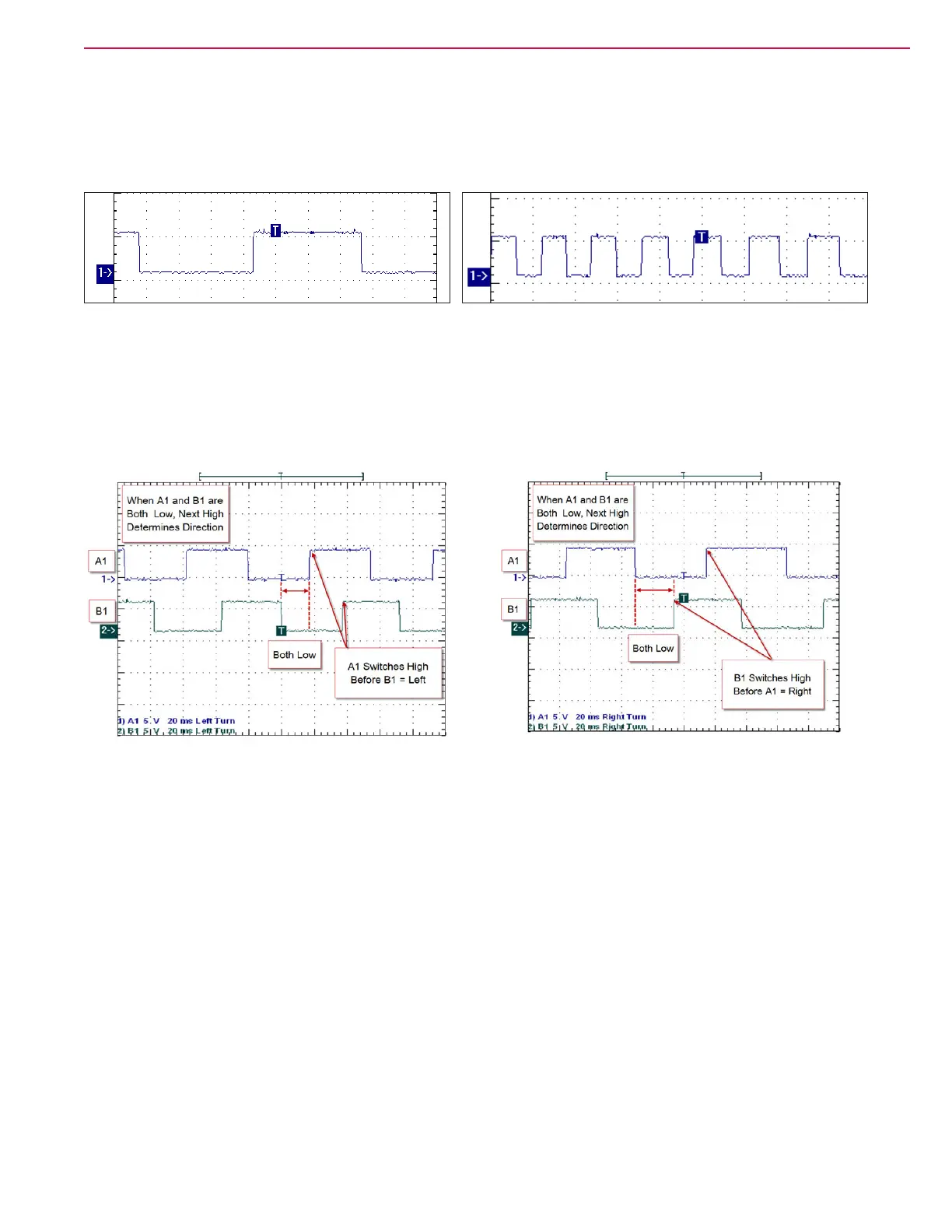
on a scope (oscilloscope) it looks like a “square wave” pattern. When the steering wheel rotation is slow, the
switching frequency is slow. This is seen as longer and fewer square wave patterns on the scope screen.
When the steering wheel rotation is faster, the switching frequency is faster. This is seen as more but
shorter patterns on the scope screen. This changing frequency is how the controller “sees” the steering wheel
rotation speed. The same is true for all 4 signals.
WaveStar : NotesSheet(2) Page: 1
Fast Rotation
WaveStar : NotesSheet(1) Page: 1
Slow Rotation
In order to determine which direction the steering wheel is rotating, the controller “looks” at two signals ( A1
and B1) at a time. These signals are intentionally offset (out of phase) from one another. This is “physically”
built into the way the encoder works. When A1 and B1 are both reporting “low”, the controller will be able to
tell which direction the steering wheel is rotating by which of the signals goes “high” rst. If A1 switches
high rst, then the wheel turning left. If B1 switches rst, the wheel is turning right. A2 and B2 are used as
an extra (redundant) pair of signals.
Right Turn Left Turn
The steering wheel sensor also contains a TFD (Torque Feedback Device). The TFD is powered on the same
circuit as the controller J5-1. Power is supplied to a coil winding inside the TFD on sensor pin 10. The power
ows through the coil, out sensor pin 9 and into controller J5-2. Inside the controller, there is a “switch” that
opens and closes rapidly to provide a “controlled” ground for the coil. When a ground is supplied, current
ows through the winding and creates a magnetic eld. As the percentage of ground time is increased, the
current ow increases causing a stronger magnetic eld to be created in the TFD. The magnetic eld creates
a “clamping” force on the TFD clutch pack, which in turn, provides “steering feel” to the operator.
There are two travel limit proximity switches. Each switch receives voltage on the same circuit as J5-1
(through the seat switch). The switches are normally open. When the cam “tooth” lines up with the switch,
the switch closes sending the voltage on to the steering controller. The right travel limit switch is connected
to J5-13. The left travel limit switch is connected to J5-19

 Loading...


