Scrub System 304Service Manual – CS7000
Brush Current Sensor
• J7-24 provides +5 volts to the Brush Current Sensor.
• J7-25 provides battery ground (B-) to the Brush Current Sensor.
• The Input from the Brush Current Sensor provides the Brush Current Sense signal to J7-27 on the A1
Controller Board. The A1 Controller Board uses this current value to run the Scrub Deck Actuator Motor
M11
in the appropriate direction to either raise or lower the scrub deck to maintain the total scrub motor
current draw within the prescribed range for the selected scrub pressure.
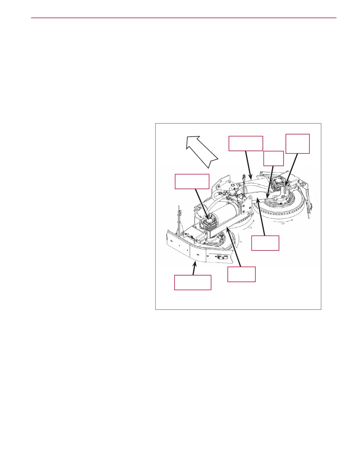
Component Locations
Scrub Motor Assemblies
The left-hand and center Scrub Motor
Assemblies
are mounted on the Deck
Weldment
. The right-hand Scrub Motor
Assembly
is mounted on the Arm Weldment
bolted to the Deck Weldment. The Right-
angle Gearboxes
are mounted on spacers
to position them correctly on the Deck and
Arm Weldments.
Right Scrub Arm Gas Spring and
Lever Arm Bracket
The Gas Spring keeps the right Arm
Weldment
and attached Side Squeegee
Assembly
extended outward during
normal scrubbing, but will allow the
Arm Weldment to pivot backward if the
right-hand Side Squeegee Assembly hits
an object or obstacle. This provides some
compliance to prevent damage to the Side
Squeegee Assembly
.
To release the Gas Spring to pivot the right
Arm Weldment backward for service or
maintenance proposes, pull the top of the
Lever Arm Bracket toward you and swing
the Arm Weldment backward.
Scrub Motor
Assembly (3)
Arm
Weldment
Side Squeegee
Assembly (2)
Right-angle
Gearbox (3)
Deck
Weldment
Front
Gas
Spring
Lever Arm
Bracket

 Loading...


