Recovery System 292Service Manual – CS7000
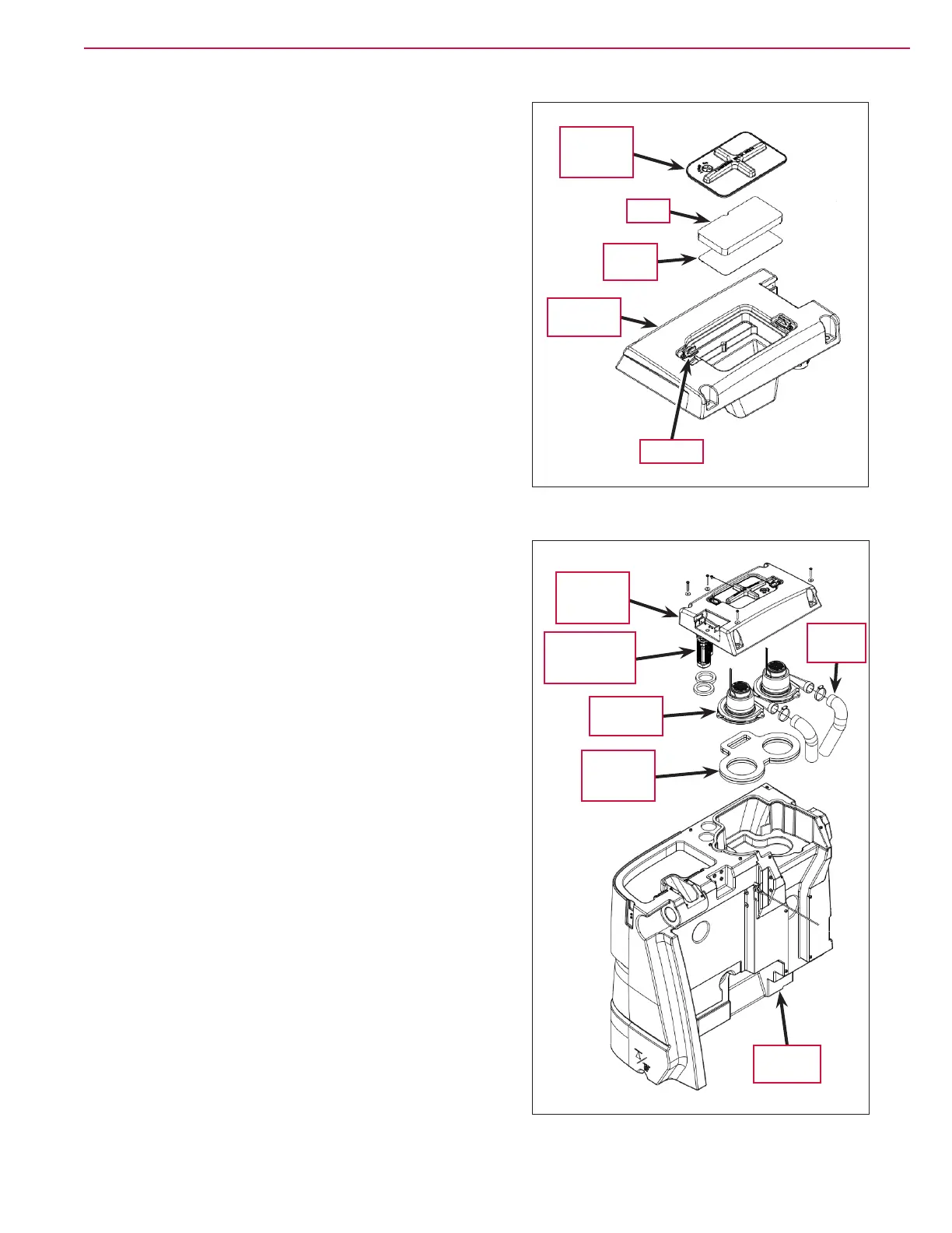
Vacuum Fan Cover Assembly
The Vacuum Fan Cover Assembly includes the Vacuum Filter
Lid Assembly
, Filter, Filter Screen and Vacuum Fan Cover.
The Vacuum Fan Cover Assembly fastens to the top of the
Recovery Tank. The two plastic Latches rotate to allow the
Vacuum Filter Lid Assembly to be removed to access the
Filter and Filter Screen.
Vacuum Motors
The Vacuum Motors sit on the Vacuum Fan Seal Assembly
in the Recovery Tank and are held in place by the Vacuum
Fan Cover Assembly
. The air from the Vacuum Motors is
exhausted through Foam Tubes no minimize noise.
Float Cage and Ball Assemblies
The Float Cage and Ball Assemblies are attached to the
Vacuum Fan Cover Assembly and prevent any recovered
water from being drawn in through the Vacuum Motors.
Vacuum
Filter Lid
Assembly
Filter
Filter
Screen
Vacuum
Fan Cover
Latch (2)
Vacuum
Fan Cover
Assembly
Vacuum
Fan Seal
Assembly
Vacuum
Motor (2)
Float Cage and
Ball Assembly
(2)
Recovery
Tank
Foam
Tube (2)

 Loading...


