Engine System - Petrol (Gasoline) 222Service Manual – Haram Captor II
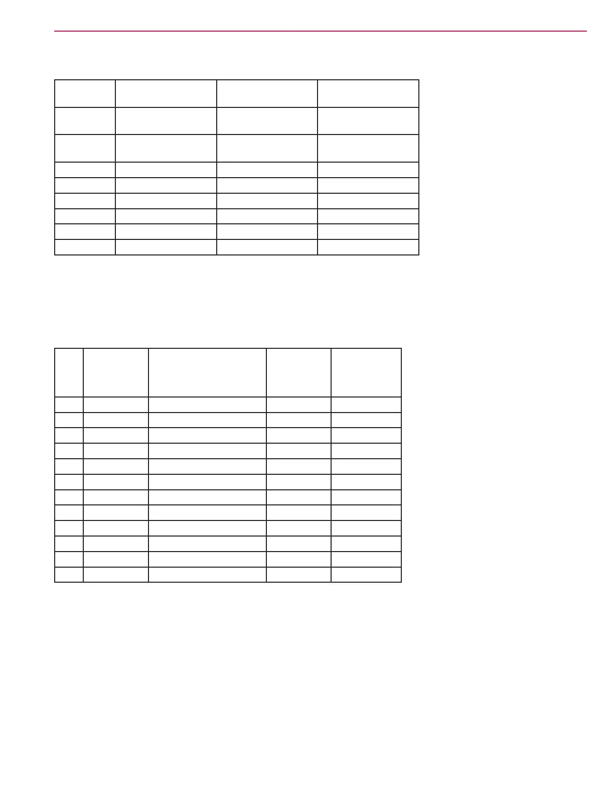
Spark Controller Measurements:
Pin Letter Wire Color on
machine
Circuit Voltage with key on
unplugged
E BLU Crank Position
Sensor
0v
F BLK Ground (And other
leg of Crank sensor)
0.004v
G Red Power Supply 11.2v
H Not used
I Not used
J BLU/BLK Coil 3 Driver 11.2v
K WHT/BLK Coil 2 Driver 11.2v
L RED/BLK Coil 1 Driver 11.2v
Governor Control System
Woodward L Series Actuator Measurements
Pin Wire Color Circuit Description Connector
Unplugged
Key On
Connector
Plugged In
Key On
1 PNK/BLK Ignition Request 11.69v 11.4v
2 Not used
3 BLK Engine RPM Sensor - -
4 GRA/BLU Throttle 1 7.79v 0.007v
5 BLK Ground 0.007v 0.007v
6 GRA/ORN Throttle 2 7.78v 0.007v
7 Not used
8 GRA/WHT Run Enable Signal 11.9v 11.0v
9 BLK/WHT Shut Down Signal 11.6v 0.028v
10 Not Used
11 CLR Engine RPM Sensor - -
12 Not Used
RPM Sensor Output (measured at the actuator Pin 3 and 11 with the connector plugged in):
• 0.68v AC when cranking
• 2.13v AC when running
Engine RPM sensor resistance - 2.07 K ohms

 Loading...


