Wheel System, Non-traction 440Service Manual – CS7000
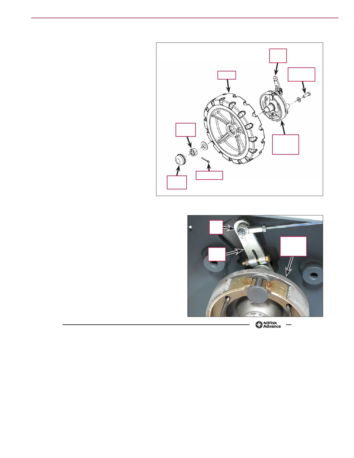
3. Remove the Grease Cap.
4. Remove the Cotter Pin, Slotted Nut and
washer.
5. Remove the Wheel from the Brake and
Spindle Assembly
.
6. Reinstall the Wheel by following the
above steps in reverse order.
To Remove and Reinstall a Brake
and Spindle Assembly
1. Jack up the machine at a designated
jacking point.
2. Install safety stands or blocks to
support the machine while you work
on it.
3. Remove the Wheel from the Brake and
Spindle Assembly
.
4. Remove the Nyloc nut and 1/4”-20 screw holding
the Rod End to the Brake Lever.
5. Remove the two 1/2”-20 hex screws and remove
the Brake and Spindle Assembly from the machine.
6. Reinstall the Brake and Spindle Assembly by
following the above steps in reverse order.
Slotted
Nut
Cotter Pin
Wheel
Brake and
Spindle
Assembly
1/2”-20 Hex
Screw
Grease
Cap
Brake
Lever
Rod
End
Brake
Lever
Brake and
Spindle
Assembly

 Loading...


