Electrical System 104Service Manual – CS7000
All models have a large connector to disconnect power from the machine. A circuit breaker panel located on
the left side of the operator foot well area provides circuit protection for multiple circuits.
The electrical system makes use of hall effect current sensors to provide amp draw information to the main
machine controller for some circuits.
Wiring Harnesses
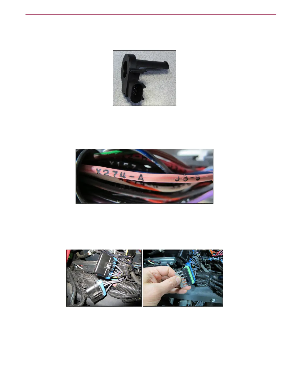
Wires are color coded and have connector information printed near each end of the wire. In the photo below,
the left end of the wire goes to connector X274 pin A and the right side of the wire goes to connector J3 pin 9.
The main harness is the same for all models. Connectors which are not used for certain models or features
have plugs covering them or may be “jumped” together as is the case for the battery interlock switch on
engine models.
There are splices in the harness that are shrink wrapped. There are also two “splice saver” connectors which
look like capped off connectors, but actually connect many wires together through a “comb” that is inserted
into the connector.
The CAN Bus wire pairs are twisted to prevent electrical interference from corrupting the messages. If any
repairs are performed on the CAN Bus wires, the wire pairs must be twisted approximately once per inch.
Current Sensor

 Loading...


