Training Guide Course No. 196514
Level 2 Maintenance, X-1000 Series Dispensing Systems 4-11 P/N 196515 (Revision A)
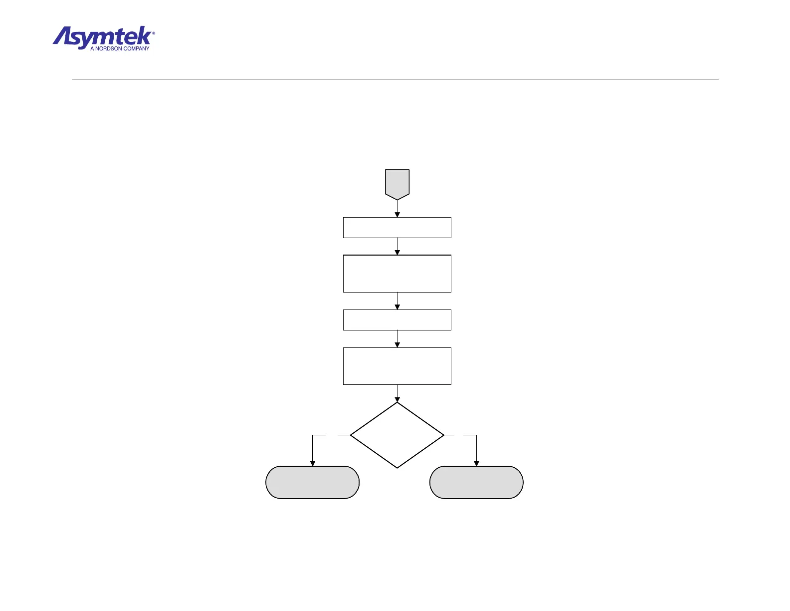
C
Switch the Main Circuit Breaker
to the OFF (0) position.
Reconnect the Servo
Interconnect A Cable (P/N 06-
4525-00) to the Main Interface
PWA.
Switch the Main Circuit Breaker
to the ON (I) position.
Measure VAC at TP4 (A+5V) and
at TP3 (A+15V) on the XY Servo
Interface PWA. (Use TP5 for
ground).
Is the Voltage correct
at the Test Points
(TPs)?
LED on the XY Servo
Interface PWA
(P/N 60-1211-00) has
failed
Servo Interconnect A
Cable (P/N 06-4525-00)
has failed.
Yes No
C
Switch the Main Circuit Breaker
to the OFF (0) position.
Reconnect the Servo
Interconnect A Cable (P/N 06-
4525-00) to the Main Interface
PWA.
Switch the Main Circuit Breaker
to the ON (I) position.
Measure VAC at TP4 (A+5V) and
at TP3 (A+15V) on the XY Servo
Interface PWA. (Use TP5 for
ground).
Is the Voltage correct
at the Test Points
(TPs)?
Is the Voltage correct
at the Test Points
(TPs)?
LED on the XY Servo
Interface PWA
(P/N 60-1211-00) has
failed
Servo Interconnect A
Cable (P/N 06-4525-00)
has failed.
Yes No
Diagram Sheet 4-2-4
Main Power Fault Isolation Procedure – Main Power Verification (Continued)

 Loading...


