Training Guide Course No. 196514
Level 2 Maintenance, X-1000 Series Dispensing Systems 4-12 P/N 196515 (Revision A)
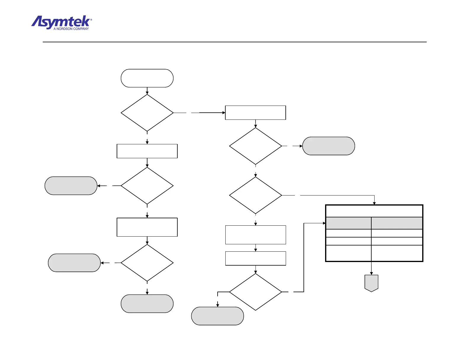
Does the green
ON (I) button stay
illuminated?
Does the green
ON (I) button stay
illuminated?
Go to XY Servo Interface
Power Verification
Procedure
Locate the power LEDs on
the XY Servo Interface PWA.
Are the green
+24V_A&B_ISO and
+24V LEDs
illuminated?
Are the green
+24V_A&B_ISO and
+24V LEDs
illuminated?
Locate the Dispense Head
Controller status LEDs on the
left side of Dispensing Head.
Are the top 3
green D16, D17,
and D18 LEDs
illuminated?
Are the top 3
green D16, D17,
and D18 LEDs
illuminated?
Go to Dispense Head
Controller Power
Verification Procedure
No system power fault.
Contact Asymtek
Technical Support if fault
reoccurs.
Locate the power LEDs on
the XY Servo Interface PWA.
Are the green 5V,
A+15V, and A+5V
LEDs illuminated?
Are the green 5V,
A+15V, and A+5V
LEDs illuminated?
Is the front or
rear EMO Button
depressed?
Is the front or
rear EMO Button
depressed?
Rotate front and rear EMO
Buttons counterclockwise
until released.
Press the green ON (I) button
on the Operator's Console.
Does the green
ON (I) button on the
Operator's Console
stay illuminated?
Does the green
ON (I) button on the
Operator's Console
stay illuminated?
Go to Main Power Fault
Isolation Procedure
Connector with Pin 1 to Pin 2
and Pin 3 to Pin 4 shorted.
Vent Switch Faker P/N 194034.
Vent Switch Faker (J9)
P/N 06-4511-00Rear EMO (J8)
P/N 06-4515-00Power Control (J5)
Cable
Power Manager
Connection
Verify the proper cables are connected to the Power Manager
as specified below:
Connector with Pin 1 to Pin 2
and Pin 3 to Pin 4 shorted.
Vent Switch Faker P/N 194034.
Vent Switch Faker (J9)
P/N 06-4511-00Rear EMO (J8)
P/N 06-4515-00Power Control (J5)
Cable
Power Manager
Connection
Verify the proper cables are connected to the Power Manager
as specified below:
Dispensing system being
in EMO state is root
cause of power fault.
A
Press the green ON (I)
button on the Operator's
Console.
No
Yes
No
Yes
No
Yes
No
Yes
No
Yes
No
Yes
Diagram Sheet 4-2-5
System Power Fault Isolation Procedure - System Power Verification

 Loading...


