Training Guide Course No. 196514
Level 2 Maintenance, X-1000 Series Dispensing Systems 4-73 PN 1965155 (Revision A)
Stop! Rotary Encoder is
root cause of following
error fault.
Manually move the Dispensing
Head to the mechanical hard
stops in the front left corner of
the dispensing chamber.
Type M101 and press [Enter] on
Keyboard. Note value returned.
Manually move the Dispensing
Head in random directions at
different speeds trying to cover
the whole dispensing chamber.
Return Dispensing Head to the
mechanical hard stops in front
left corner of the chamber.
Again, type M101 and press
[Enter]. Note the value returned.
Repeat the above steps three
times.
Is difference of
any set of values
greater than 200
counts?
Record the difference between
the numeric values noted.
X-axis Rotary Encoder
is not
root cause of fault.
Go to Y-axis Rotary
Encoder Verification
Yes No
A
Remove Servo Motor Cover
located at the rear of dispensing
system below the Servo Shelf.
Rotary Encoder Cable (P/N 06-
4535-00) should be connected to
the X-axis Servo Motor Amplifier
at J3 labeled Rotary Encoder and
the X-axis Servo Motor.
At the X-axis Servo Motor, the
black wire on Rotary Encoder
Cable should be orientated to
Pin 1 labeled GND with the
copper lead facing you.
Carefully remove the Servo
Motor Connector (leads are
fragile) and check for damage.
Are any of the
Servo Motor
Connector leads
damaged?
Servo Motor (P/N 62-
1650-01) has failed.
Yes No
Manually move the Dispensing
Head in the X-axis.
Again, type M101 and press
[Enter]. Note the value returned.
Are the two
numerical values
different?
In the Tools Menu, click on
the Terminal icon.
From the FmNT Main Menu,
click on the Tools icon.
Under the Terminal icon, click
on the Dispenser icon.
Press the black OFF (0)
button on the Operator’s
Console.
In Dispenser Terminal
Window, type M101 and
press [Enter]. Note value
returned.
Yes No
Stop! Rotary Encoder is
root cause of following
error fault.
Manually move the Dispensing
Head to the mechanical hard
stops in the front left corner of
the dispensing chamber.
Type M101 and press [Enter] on
Keyboard. Note value returned.
Manually move the Dispensing
Head in random directions at
different speeds trying to cover
the whole dispensing chamber.
Return Dispensing Head to the
mechanical hard stops in front
left corner of the chamber.
Again, type M101 and press
[Enter]. Note the value returned.
Repeat the above steps three
times.
Is difference of
any set of values
greater than 200
counts?
Record the difference between
the numeric values noted.
X-axis Rotary Encoder
is not
root cause of fault.
Go to Y-axis Rotary
Encoder Verification
Yes No
Manually move the Dispensing
Head to the mechanical hard
stops in the front left corner of
the dispensing chamber.
Type M101 and press [Enter] on
Keyboard. Note value returned.
Manually move the Dispensing
Head in random directions at
different speeds trying to cover
the whole dispensing chamber.
Return Dispensing Head to the
mechanical hard stops in front
left corner of the chamber.
Again, type M101 and press
[Enter]. Note the value returned.
Repeat the above steps three
times.
Is difference of
any set of values
greater than 200
counts?
Is difference of
any set of values
greater than 200
counts?
Record the difference between
the numeric values noted.
X-axis Rotary Encoder
is not
root cause of fault.
Go to Y-axis Rotary
Encoder Verification
Yes No
A
Remove Servo Motor Cover
located at the rear of dispensing
system below the Servo Shelf.
Rotary Encoder Cable (P/N 06-
4535-00) should be connected to
the X-axis Servo Motor Amplifier
at J3 labeled Rotary Encoder and
the X-axis Servo Motor.
At the X-axis Servo Motor, the
black wire on Rotary Encoder
Cable should be orientated to
Pin 1 labeled GND with the
copper lead facing you.
Carefully remove the Servo
Motor Connector (leads are
fragile) and check for damage.
Are any of the
Servo Motor
Connector leads
damaged?
Servo Motor (P/N 62-
1650-01) has failed.
Yes No
A
Remove Servo Motor Cover
located at the rear of dispensing
system below the Servo Shelf.
Rotary Encoder Cable (P/N 06-
4535-00) should be connected to
the X-axis Servo Motor Amplifier
at J3 labeled Rotary Encoder and
the X-axis Servo Motor.
At the X-axis Servo Motor, the
black wire on Rotary Encoder
Cable should be orientated to
Pin 1 labeled GND with the
copper lead facing you.
Carefully remove the Servo
Motor Connector (leads are
fragile) and check for damage.
Are any of the
Servo Motor
Connector leads
damaged?
Are any of the
Servo Motor
Connector leads
damaged?
Servo Motor (P/N 62-
1650-01) has failed.
Yes No
Manually move the Dispensing
Head in the X-axis.
Again, type M101 and press
[Enter]. Note the value returned.
Are the two
numerical values
different?
Are the two
numerical values
different?
In the Tools Menu, click on
the Terminal icon.
From the FmNT Main Menu,
click on the Tools icon.
Under the Terminal icon, click
on the Dispenser icon.
Press the black OFF (0)
button on the Operator’s
Console.
In Dispenser Terminal
Window, type M101 and
press [Enter]. Note value
returned.
Yes No
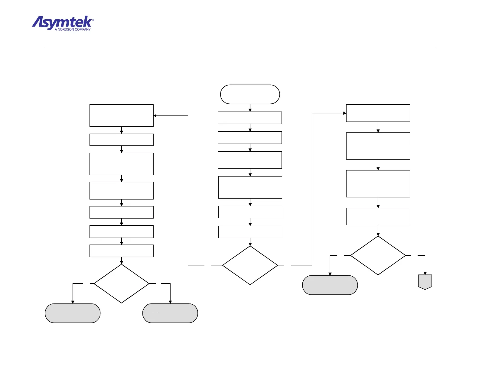
Diagram Sheet 4-6-4
PMAC Rotary Encoders Fault Isolation Procedure – X-Axis Rotary Encoder Verification

 Loading...


