Training Guide Course No. 196514
Level 2 Maintenance, X-1000 Series Dispensing Systems 4-76 P/N 196515 (Revision A)
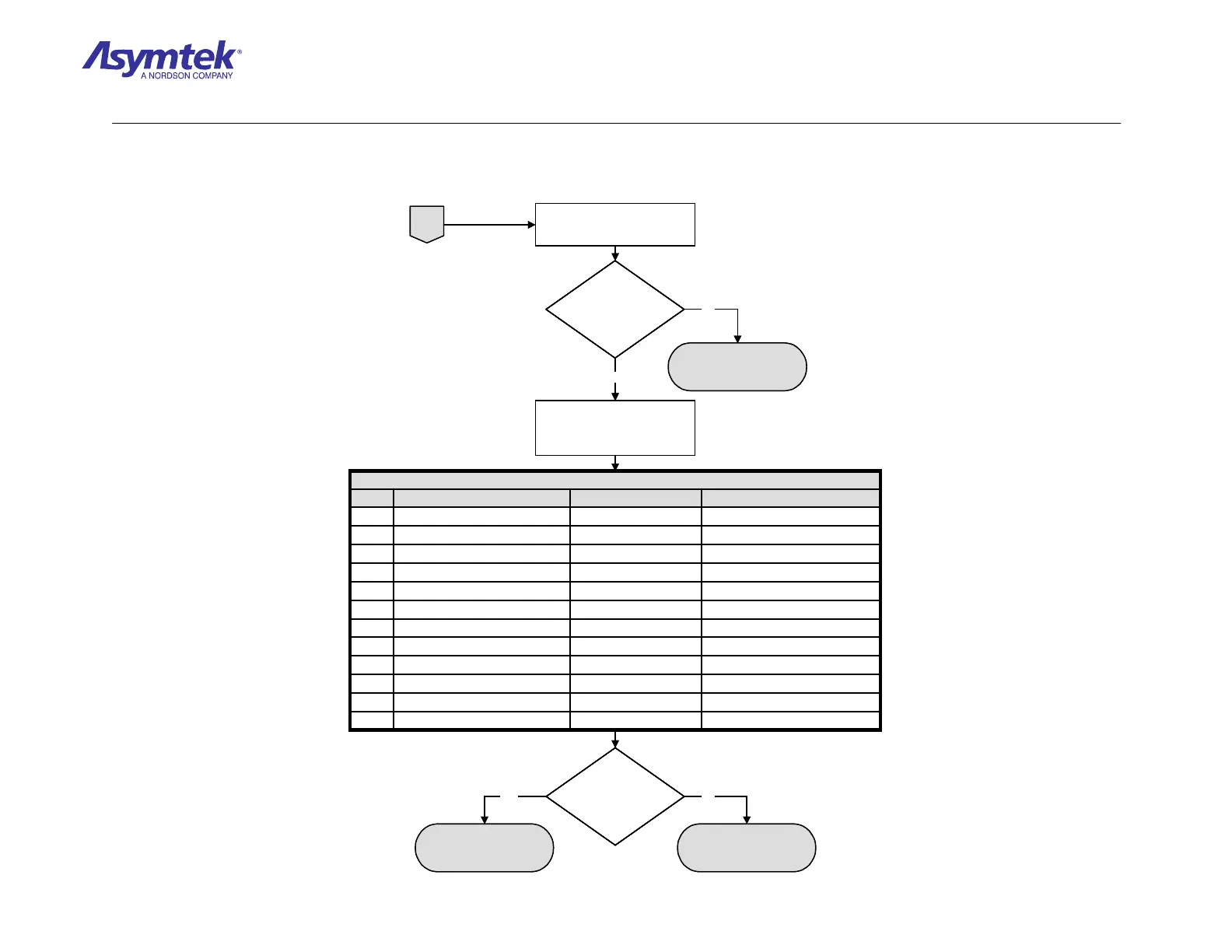
Check continuity of Rotary
Encoder Cable
(P/N 06-4535-00).
Does the Cable have
continuity?
The isolated part has
failed
Y-axis Rotary Encoder
(P/N 62-1650-01) has
failed
A
Check continuity of signal
routing from the Y-axis
Rotary Encoder as specified
in Table 2.
Pin 14 at J8 PMAC ControllerCable P/N 06-4523-00Pin 14 at J9 (Main Interface)A
Pin 13 at J8 PMAC ControllerCable P/N 06-4523-00Pin 13 at J9 (Main Interface)B
Pin 14 at J9 (Main Interface)Main Interface PWAPin 22 at J29 (Main Interface)A
Pin 13 at J9 (Main Interface)Main Interface PWAPin 23 at J29 (Main Interface)B
Pin 22 at J29 (Main Interface)Cable P/N 06-4525-00Pin 22 at J19 (XY Servo Interface)A
Pin 23 at J29 (Main Interface)Cable P/N 06-4525-00Pin 23 at J19 (XY Servo Interface)B
Pin 22 at J19 (XY Servo Interface)XY Servo Interface PWAPin 13 at J9 (XY Servo Interface)A
Pin 23 at J19 (XY Servo Interface)XY Servo Interface PWAPin 14 at J9 (XY Servo Interface)B
Pin 13 at J9 (XY Servo Interface)Cable P/N 06-0403-00Pin 13 at J5 (Servo Amp)A
Pin 14 at J9 (XY Servo Interface)Cable P/N 06-0403-00Pin 14 at J5 (Servo Amp)B
Pin 13 at J5 (Servo Amp)Y-axis Servo Amp PWAPin 5 at J3 (Servo Amp)A
Pin 14 at J5 (Servo Amp)Y-axis Servo Amp PWAPin 3 at J3 (Servo Amp)B
To (PWA)ViaFrom (PWA)Signal
TABLE 2 – Y-Axis Rotary Signal Routing
Is there continuity
of signal routing for
Y-axis Rotary
Encoder?
Yes No
Rotary Encoder Cable
(P/N 06-4535-00) has
failed.
No
Yes
Check continuity of Rotary
Encoder Cable
(P/N 06-4535-00).
Does the Cable have
continuity?
Does the Cable have
continuity?
The isolated part has
failed
Y-axis Rotary Encoder
(P/N 62-1650-01) has
failed
A
Check continuity of signal
routing from the Y-axis
Rotary Encoder as specified
in Table 2.
Pin 14 at J8 PMAC ControllerCable P/N 06-4523-00Pin 14 at J9 (Main Interface)A
Pin 13 at J8 PMAC ControllerCable P/N 06-4523-00Pin 13 at J9 (Main Interface)B
Pin 14 at J9 (Main Interface)Main Interface PWAPin 22 at J29 (Main Interface)A
Pin 13 at J9 (Main Interface)Main Interface PWAPin 23 at J29 (Main Interface)B
Pin 22 at J29 (Main Interface)Cable P/N 06-4525-00Pin 22 at J19 (XY Servo Interface)A
Pin 23 at J29 (Main Interface)Cable P/N 06-4525-00Pin 23 at J19 (XY Servo Interface)B
Pin 22 at J19 (XY Servo Interface)XY Servo Interface PWAPin 13 at J9 (XY Servo Interface)A
Pin 23 at J19 (XY Servo Interface)XY Servo Interface PWAPin 14 at J9 (XY Servo Interface)B
Pin 13 at J9 (XY Servo Interface)Cable P/N 06-0403-00Pin 13 at J5 (Servo Amp)A
Pin 14 at J9 (XY Servo Interface)Cable P/N 06-0403-00Pin 14 at J5 (Servo Amp)B
Pin 13 at J5 (Servo Amp)Y-axis Servo Amp PWAPin 5 at J3 (Servo Amp)A
Pin 14 at J5 (Servo Amp)Y-axis Servo Amp PWAPin 3 at J3 (Servo Amp)B
To (PWA)ViaFrom (PWA)Signal
TABLE 2 – Y-Axis Rotary Signal Routing
Is there continuity
of signal routing for
Y-axis Rotary
Encoder?
Is there continuity
of signal routing for
Y-axis Rotary
Encoder?
Yes No
Rotary Encoder Cable
(P/N 06-4535-00) has
failed.
No
Yes
Diagram Sheet 4-6-7
PMAC Rotary Encoders Fault Isolation Procedure – Y-Axis Rotary Encoder Verification (Continued)

 Loading...


