Training Guide Course No. 196514
Level 2 Maintenance, X-1000 Series Dispensing Systems 4-83 PN 1965155 (Revision A)
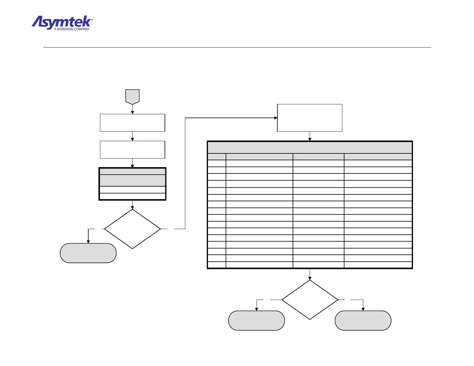
A
Check continuity of Y-axis
Linear Encoder signal routing
from the XY Servo Interface
PWA to the PMAC Controller
as specified in Table 7.
The isolated part has
failed
PMAC Controller (P/N 07-
0735-01) may have failed.
Is there continuity
of signal routing for
Y-axis Linear
Encoder?
Yes No
Does Cable have
continuity between the
pins specified in
Table 6?
Disconnect Y-axis Linear
Encoder Cable from J23 on XY
Servo Interface PWA.
Check continuity of Y-axis Linear
Encoder Cable as specified in
Table 6.
Pin 12 at J8 PMAC ControllerCable (P/N 06-4523-00)Pin 12 at J9 (Main Interface)B/
Pin 10 at J8 PMAC ControllerCable (P/N 06-4523-00)Pin 10 at J9 (Main Interface)B
Pin 16 at J8 PMAC ControllerCable (P/N 06-4523-00)Pin 16 at J9 (Main Interface)A/
Pin 14 at J8 PMAC ControllerCable (P/N 06-4523-00)Pin 14 at J9 (Main Interface)A
Pin 12 at J9 (Main Interface)Main Interface PWAPin 3 at J29 (Main Interface)B/
Pin 10 at J9 (Main Interface)Main Interface PWAPin 2 at J29 (Main Interface)B
Pin 16 at J9 (Main Interface)Main Interface PWAPin 5 at J29 (Main Interface)A/
Pin 14 at J9 (Main Interface)Main Interface PWAPin 4 at J29 (Main Interface)A
Pin 3 at J29 (Main Interface)Cable (P/N 06-4525-00)Pin 3 at J19 (XY Servo Interface)B/
Pin 2 at J29 (Main Interface)Cable (P/N 06-4525-00)Pin 2 at J19 (XY Servo Interface)B
Pin 5 at J29 (Main Interface)Cable (P/N 06-4525-00)Pin 5 at J19 (XY Servo Interface)A/
Pin 4 at J29 (Main Interface)Cable (P/N 06-4525-00)Pin 4 at J19 (XY Servo Interface)A
Pin 3 at J19 (XY Servo Interface)XY Servo Interface PWAPin 8 at J23 (XY Servo Interface)B/
Pin 2 at J19 (XY Servo Interface)XY Servo Interface PWAPin 6 at J23 (XY Servo Interface)B
Pin 5 at J19 (XY Servo Interface)XY Servo Interface PWAPin 4 at J23 (XY Servo Interface)A/
Pin 4 at J19 (XY Servo Interface)XY Servo Interface PWAPin 2 at J23 (XY Servo Interface)A
To (PWA)ViaFrom (PWA)Signal
Table 7
Y-Axis Linear Encoder Signal Routing
Yes
Linear Encoder Cable (P/N
194986) has failed.
No
Pin 3 to Pin 7
Pin 1 to Pin 5
Encoder (P/N 194986)
Cable Pin Connections
Table 6
A
Check continuity of Y-axis
Linear Encoder signal routing
from the XY Servo Interface
PWA to the PMAC Controller
as specified in Table 7.
The isolated part has
failed
PMAC Controller (P/N 07-
0735-01) may have failed.
Is there continuity
of signal routing for
Y-axis Linear
Encoder?
Is there continuity
of signal routing for
Y-axis Linear
Encoder?
Yes No
Does Cable have
continuity between the
pins specified in
Table 6?
Does Cable have
continuity between the
pins specified in
Table 6?
Disconnect Y-axis Linear
Encoder Cable from J23 on XY
Servo Interface PWA.
Check continuity of Y-axis Linear
Encoder Cable as specified in
Table 6.
Pin 12 at J8 PMAC ControllerCable (P/N 06-4523-00)Pin 12 at J9 (Main Interface)B/
Pin 10 at J8 PMAC ControllerCable (P/N 06-4523-00)Pin 10 at J9 (Main Interface)B
Pin 16 at J8 PMAC ControllerCable (P/N 06-4523-00)Pin 16 at J9 (Main Interface)A/
Pin 14 at J8 PMAC ControllerCable (P/N 06-4523-00)Pin 14 at J9 (Main Interface)A
Pin 12 at J9 (Main Interface)Main Interface PWAPin 3 at J29 (Main Interface)B/
Pin 10 at J9 (Main Interface)Main Interface PWAPin 2 at J29 (Main Interface)B
Pin 16 at J9 (Main Interface)Main Interface PWAPin 5 at J29 (Main Interface)A/
Pin 14 at J9 (Main Interface)Main Interface PWAPin 4 at J29 (Main Interface)A
Pin 3 at J29 (Main Interface)Cable (P/N 06-4525-00)Pin 3 at J19 (XY Servo Interface)B/
Pin 2 at J29 (Main Interface)Cable (P/N 06-4525-00)Pin 2 at J19 (XY Servo Interface)B
Pin 5 at J29 (Main Interface)Cable (P/N 06-4525-00)Pin 5 at J19 (XY Servo Interface)A/
Pin 4 at J29 (Main Interface)Cable (P/N 06-4525-00)Pin 4 at J19 (XY Servo Interface)A
Pin 3 at J19 (XY Servo Interface)XY Servo Interface PWAPin 8 at J23 (XY Servo Interface)B/
Pin 2 at J19 (XY Servo Interface)XY Servo Interface PWAPin 6 at J23 (XY Servo Interface)B
Pin 5 at J19 (XY Servo Interface)XY Servo Interface PWAPin 4 at J23 (XY Servo Interface)A/
Pin 4 at J19 (XY Servo Interface)XY Servo Interface PWAPin 2 at J23 (XY Servo Interface)A
To (PWA)ViaFrom (PWA)Signal
Table 7
Y-Axis Linear Encoder Signal Routing
Yes
Linear Encoder Cable (P/N
194986) has failed.
No
Pin 3 to Pin 7
Pin 1 to Pin 5
Encoder (P/N 194986)
Cable Pin Connections
Table 6
Pin 3 to Pin 7
Pin 1 to Pin 5
Encoder (P/N 194986)
Cable Pin Connections
Table 6
Diagram Sheet 4-6-14
PMAC Linear Encoders Fault Isolation Procedure – Y-Axis Linear Encoder Verification (Continued)

 Loading...


