Training Guide Course No. 196514
Level 2 Maintenance, X-1000 Series Dispensing Systems 4-86 P/N 196515 (Revision A)
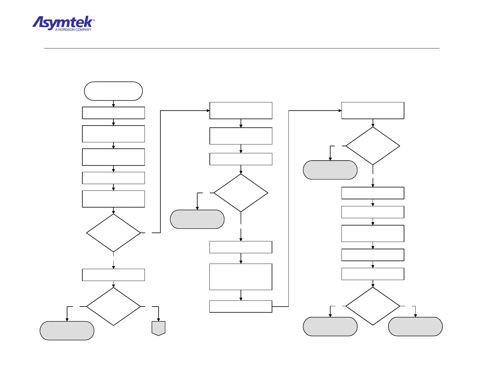
Is the reading greater
than 4 VDC?
Z-Head Interconnect
Cable (P/N 06-4550-00)
has failed.
XY Servo Interface Board
(P/N 60-1211-00) has
failed.
Yes No
Exit FmNT, shut down
Windows NT and press the
black OFF (0) button on the
Operator’s Console
Switch the Main Circuit Breaker
to the OFF (0) position.
Manually move the Dispensing
Head to the middle of the
dispensing chamber.
Remove the white cover from the
X-axis Home Sensor Cable (P/N
06-4540-00) connection.
Switch the Main Circuit Breaker
to the ON (I) position.
Measure VDC between Pin 1
and Pin 2 of the X-axis Cable
(P/N 06-4540-00).
Is the reading greater
than 4 VDC?
Measure VDC between Pin 1
and Pin 4 on X-axis Home Cable.
Is the reading greater
than 4 VDC?
Yes
Locate J3 on the Z-Servo
Interface PWA at the rear of the
Dispensing Head.
Remove X-axis Home Sensor
Cable (P/N 06-4540-00) from
connector.
Measure VDC between Pin 1
and 2 of the J3 connector.
Is the reading greater
than 4 VDC?
No
Home/Limit Switch PWA
(P/N 60-0785-00) has
failed.
X-axis Home Sensor
Cable (P/N 06-4540-00)
has failed.
Switch the Main Circuit Breaker
to the ON (l) position.
Measure VDC between Pin 1 and
Pin 23 of Z-head Interconnect
Cable (P/N 06-4550-00).
Switch the Main Circuit Breaker
to the OFF ()) position.
Disconnect the Z-Head
Interconnect Cable (P/N 06-
4550-00) from rear of Dispensing
Head at the Z Servo Interface
PWA connection J2 connector.
Is the reading greater
than 4 VDC?
YesNo
No
Yes
Switch the Main Circuit Breaker
to the OFF (0) position.
Locate J31 on the XY Servo
Interface PWA.
Disconnect the Z-Head
Interconnect Cable (P/N 06-
4550-00).
Switch the Main Circuit Breaker
to the ON (I) position.
Measure VDC between Pin 1
and Pin 23 at connector J31.
No
A
Z-Head Servo Interface
PWA (P/N 60-120-01) has
failed.
Yes
Is the reading greater
than 4 VDC?
Z-Head Interconnect
Cable (P/N 06-4550-00)
has failed.
XY Servo Interface Board
(P/N 60-1211-00) has
failed.
Yes No
Is the reading greater
than 4 VDC?
Is the reading greater
than 4 VDC?
Z-Head Interconnect
Cable (P/N 06-4550-00)
has failed.
XY Servo Interface Board
(P/N 60-1211-00) has
failed.
Yes No
Exit FmNT, shut down
Windows NT and press the
black OFF (0) button on the
Operator’s Console
Switch the Main Circuit Breaker
to the OFF (0) position.
Manually move the Dispensing
Head to the middle of the
dispensing chamber.
Remove the white cover from the
X-axis Home Sensor Cable (P/N
06-4540-00) connection.
Switch the Main Circuit Breaker
to the ON (I) position.
Measure VDC between Pin 1
and Pin 2 of the X-axis Cable
(P/N 06-4540-00).
Is the reading greater
than 4 VDC?
Is the reading greater
than 4 VDC?
Measure VDC between Pin 1
and Pin 4 on X-axis Home Cable.
Is the reading greater
than 4 VDC?
Is the reading greater
than 4 VDC?
Yes
Locate J3 on the Z-Servo
Interface PWA at the rear of the
Dispensing Head.
Remove X-axis Home Sensor
Cable (P/N 06-4540-00) from
connector.
Measure VDC between Pin 1
and 2 of the J3 connector.
Is the reading greater
than 4 VDC?
Is the reading greater
than 4 VDC?
No
Home/Limit Switch PWA
(P/N 60-0785-00) has
failed.
X-axis Home Sensor
Cable (P/N 06-4540-00)
has failed.
Switch the Main Circuit Breaker
to the ON (l) position.
Measure VDC between Pin 1 and
Pin 23 of Z-head Interconnect
Cable (P/N 06-4550-00).
Switch the Main Circuit Breaker
to the OFF ()) position.
Disconnect the Z-Head
Interconnect Cable (P/N 06-
4550-00) from rear of Dispensing
Head at the Z Servo Interface
PWA connection J2 connector.
Is the reading greater
than 4 VDC?
Is the reading greater
than 4 VDC?
YesNo
No
Yes
Switch the Main Circuit Breaker
to the OFF (0) position.
Locate J31 on the XY Servo
Interface PWA.
Disconnect the Z-Head
Interconnect Cable (P/N 06-
4550-00).
Switch the Main Circuit Breaker
to the ON (I) position.
Measure VDC between Pin 1
and Pin 23 at connector J31.
No
A
Z-Head Servo Interface
PWA (P/N 60-120-01) has
failed.
Yes
Diagram Sheet 4-6-17
PMAC Home Sensor Fault Isolation Procedure – X-Axis Home Sensor Verification

 Loading...


