Training Guide Course No. 196514
Level 2 Maintenance, X-1000 Series Dispensing Systems 4-106 P/N 196515 (Revision A)
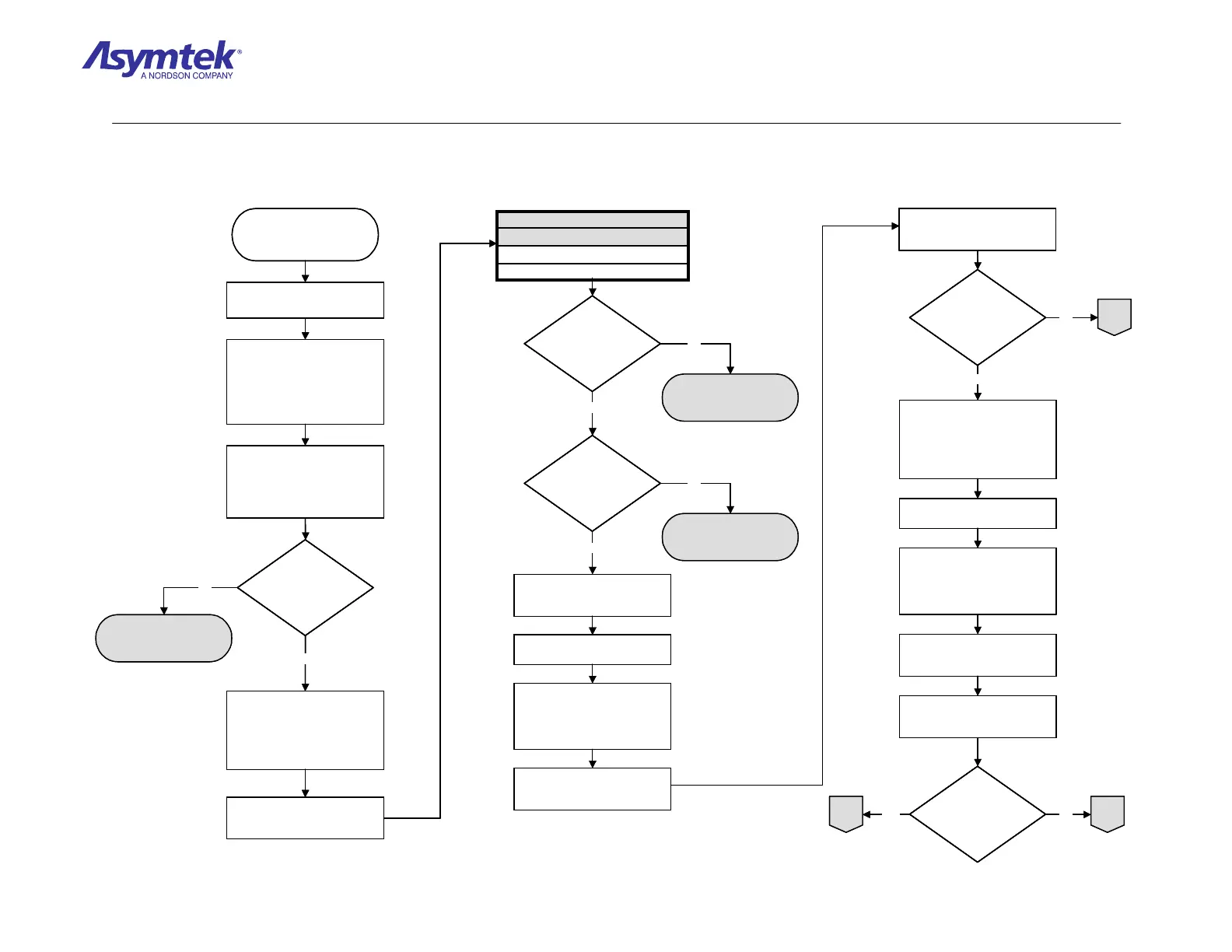
Exit FmNT, shut down
Windows NT and press the
black OFF (0) button on the
Operator’s Console
As Motors turn,
do the six LEDs
appear to illuminate
intermittently?
Remove the Conveyor
Controller Cover.
Connect the Power Cable to
the facility outlet, switch Main
Circuit Breaker to ON (I)
position, press the green ON
(I) button on the Operator’s
Console, and enter FmNT.
While jogging the Belt
Motors, observe the six LEDs
(labeled D32 to D36) located
in the middle of Conveyor
Controller Lower Board.
Exit FmNT, shut down Windows
NT, press black OFF (0) button
on the Operator’s Console,
switch Main Circuit Breaker to
OFF (0), and disconnect Power
Cable from facility outlet.
B
Conveyor Controller
(P/N 62-1677-00 on
X1020, or P/N 62-1676
on X1010) has failed
Check resistance between
connector pins on both Belt
Motors as specified in Table 1
Between Pin 3 and Pin 4
Between Pin 1 and Pin 2
CONNECTOR PINS
TABLE 1
Is resistance 1.5
ohms between pins on
the Front Belt Motor
Connector?
Is resistance 1.5
ohms between pins on
the Rear Belt Motor
Connector?
Disconnect the Width Motor
Connector from the Conveyor
Interconnect PWA.
Install Rear Belt Motor connector
in the Width Motor connector.
Connect the Power Cable to
facility outlet, switch Main Circuit
Breaker to ON (I), press green
ON (I) button on the Operator’s
Console, and enter FmNT.
From any FmNT window, click on
the Jog icon, or press [Ctrl + J]
on the Keyboard.
Click on Conveyor and use the
Jog Controls to change the
Conveyor width.
Did the Rear Belt
Motor turn?
Exit FmNT, shut down Windows
NT, press the black OFF (0)
button on the Operator’s Console,
switch Main Circuit Breaker to
OFF (0), and disconnect Power
Cable from the facility outlet.
Install Front Belt Motor connector
in the Width Motor receptacle.
Connect the Power Cable to the
facility outlet, switch Main Circuit
Breaker to ON (I), press the
green ON (I) button on Operator’s
Console, and enter FmNT.
From any FmNT window, click on
the Jog icon, or press [Ctrl + J]
on the Keyboard.
Click on Conveyor and use the
Jog Controls to change the
Conveyor width.
Did the Front Belt
Motor turn?
Front Belt Motor (P/N 07-
0716-00) has failed
Rear Belt Motor (P/N 07-
0716-00) has failed.
A
B
Yes
No
Yes
No
Yes
No
Yes
No
Yes No
Exit FmNT, shut down
Windows NT and press the
black OFF (0) button on the
Operator’s Console
As Motors turn,
do the six LEDs
appear to illuminate
intermittently?
As Motors turn,
do the six LEDs
appear to illuminate
intermittently?
Remove the Conveyor
Controller Cover.
Connect the Power Cable to
the facility outlet, switch Main
Circuit Breaker to ON (I)
position, press the green ON
(I) button on the Operator’s
Console, and enter FmNT.
While jogging the Belt
Motors, observe the six LEDs
(labeled D32 to D36) located
in the middle of Conveyor
Controller Lower Board.
Exit FmNT, shut down Windows
NT, press black OFF (0) button
on the Operator’s Console,
switch Main Circuit Breaker to
OFF (0), and disconnect Power
Cable from facility outlet.
B
Conveyor Controller
(P/N 62-1677-00 on
X1020, or P/N 62-1676
on X1010) has failed
Check resistance between
connector pins on both Belt
Motors as specified in Table 1
Between Pin 3 and Pin 4
Between Pin 1 and Pin 2
CONNECTOR PINS
TABLE 1
Between Pin 3 and Pin 4
Between Pin 1 and Pin 2
CONNECTOR PINS
TABLE 1
Is resistance 1.5
ohms between pins on
the Front Belt Motor
Connector?
Is resistance 1.5
ohms between pins on
the Front Belt Motor
Connector?
Is resistance 1.5
ohms between pins on
the Rear Belt Motor
Connector?
Is resistance 1.5
ohms between pins on
the Rear Belt Motor
Connector?
Disconnect the Width Motor
Connector from the Conveyor
Interconnect PWA.
Install Rear Belt Motor connector
in the Width Motor connector.
Connect the Power Cable to
facility outlet, switch Main Circuit
Breaker to ON (I), press green
ON (I) button on the Operator’s
Console, and enter FmNT.
From any FmNT window, click on
the Jog icon, or press [Ctrl + J]
on the Keyboard.
Click on Conveyor and use the
Jog Controls to change the
Conveyor width.
Did the Rear Belt
Motor turn?
Did the Rear Belt
Motor turn?
Exit FmNT, shut down Windows
NT, press the black OFF (0)
button on the Operator’s Console,
switch Main Circuit Breaker to
OFF (0), and disconnect Power
Cable from the facility outlet.
Install Front Belt Motor connector
in the Width Motor receptacle.
Connect the Power Cable to the
facility outlet, switch Main Circuit
Breaker to ON (I), press the
green ON (I) button on Operator’s
Console, and enter FmNT.
From any FmNT window, click on
the Jog icon, or press [Ctrl + J]
on the Keyboard.
Click on Conveyor and use the
Jog Controls to change the
Conveyor width.
Did the Front Belt
Motor turn?
Did the Front Belt
Motor turn?
Front Belt Motor (P/N 07-
0716-00) has failed
Rear Belt Motor (P/N 07-
0716-00) has failed.
A
B
Yes
No
Yes
No
Yes
No
Yes
No
Yes No
Diagram Sheet 4-8-7
Conveyor Motors Fault Isolation Procedure – Rear/Front Belt Motor Verification

 Loading...


