3 - 15
3 Specifications
AC Servomotors/Servo Drives 1S-series with Built-in EtherCAT® Communications User’s Manual (I586)
3-1 Servo Drive Specifications
3
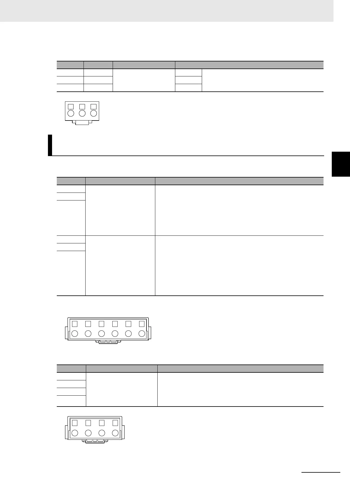
3-1-4 Main Circuit and Motor Connections
Motor Connector (CNC) Specifications
Main Circuit Connector A (CNA) Specifications
Main Circuit Connector B (CNB) Specifications
Pin No. Symbol Name Specifications
1 U Motor connection termi-
nals
Phase U These are output terminals to the Servomotor.
2 V Phase V
3 W Phase W
R88D-1SN15H-ECT/-1SN20H-ECT/-1SN30H-ECT/-1SN06F-ECT/
-1SN10F-ECT /-1SN15F-ECT/-1SN20F-ECT/-1SN30F-ECT
Symbol Name Specifications
B1 External Regeneration
Resistor connection termi-
nals
When the Internal Regeneration Resistor is used:
• Open between B1 and B2.
• Short-circuit B2 and B3.
When the External Regeneration Resistor is used:
• Connect the External Regeneration Resistor between B1 and B2.
• Open between B2 and B3.
B2
B3
L3 Main circuit power supply
input
R88D-1SN15H-ECT
Single-phase
*1
200 to 240 VAC (170 to 252 V) 50/60 Hz (47.5 to 63
Hz)
R88D-1SN15H-ECT/-1SN20H-ECT/-1SN30H-ECT
3-phase 200 to 240 VAC (170 to 252 V) 50/60 Hz (47.5 to 63 Hz)
R88D-1SNF-ECT
3-phase 380 to 480 VAC (323 to 504 V) 50/60 Hz (47.5 to 63 Hz)
*1. For single-phase, connect between any two phases out of the following: L1, L2, and L3.
L2
L1
Symbol Name Specifications
N3 DC reactor connection ter-
minals
When the DC reactor is not used:
• Short-circuit N1 and N2.
When the DC reactor is used:
• Connect the DC reactor between N1 and N2.
N2
N1
P

 Loading...

