4 - 63
4 Configuration and Wiring
AC Servomotors/Servo Drives 1S-series with Built-in EtherCAT® Communications User’s Manual (I586)
4-3 Wiring Conforming to EMC Directives
4
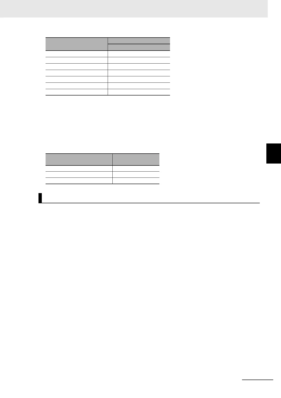
4-3-2 Selecting Connection Component
The value of the inrush current varies depending on the input voltage to the Servo Drive. The values
shown above are for the following input voltages.
Selection of Leakage Breaker
• Select a leakage breaker which is made for high frequency and surge resistance.
• When you determine the threshold value for leakage current detection, add the total leakage cur-
rent from all devices that are connected to the same breaker.
• Refer to the catalogs from the manufacturers for details on how to select a leakage breaker and
ensure a sufficient margin.
R88D-1SN10F-ECT 32 A
R88D-1SN15F-ECT 32 A
R88D-1SN20F-ECT 32 A
R88D-1SN30F-ECT 32 A
R88D-1SN55F-ECT 68 A
R88D-1SN75F-ECT 68 A
R88D-1SN150F-ECT 68 A
*1. If an external regeneration resistor is attached, the inrush
currents of the main circuit power supplies in the above table
will be increased.
(Increase in current = √2 × main circuit power supply volt-
age/external regeneration resistance)
Model
Main circuit power
supply voltage
R88D-1SNL-ECT 120 VAC
R88D-1SNH-ECT 240 VAC
R88D-1SNF-ECT 480 VAC
Leakage Breaker
Servo Drive model
Inrush current (Ao-p)
Main circuit power supply

 Loading...

