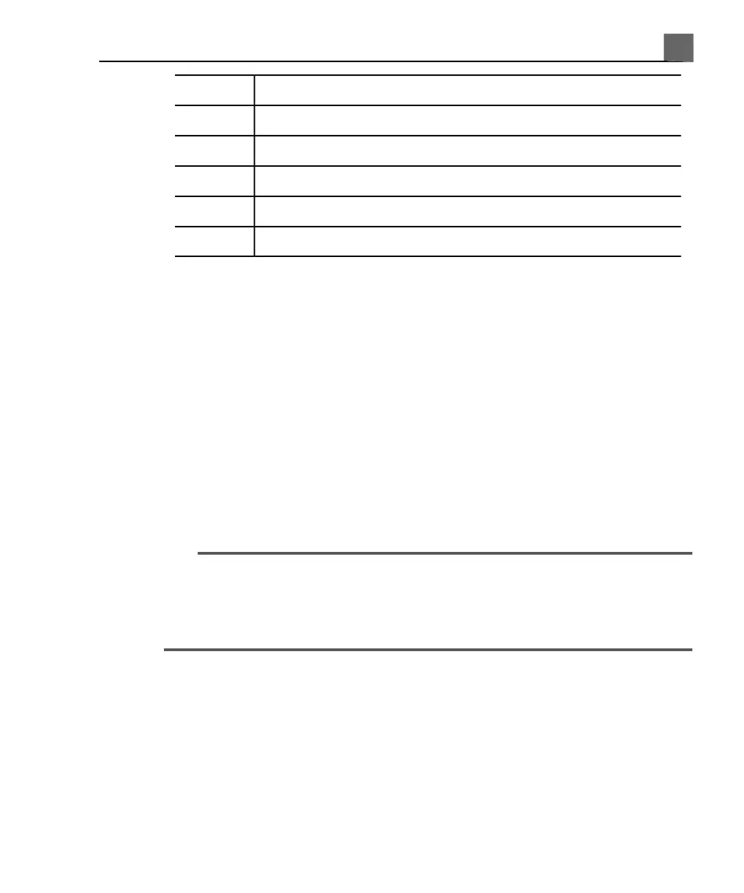
DefinitionSymbol
Line polarity switchS2
Microammeter switchS3
Line mains supplyL
Neutral mains supplyN
Earth groundE
Current I, driven by line supply e, flows through all stray capacitances between
the primary wiring and the ultrasound system’s metal chassis. Ordinarily, current
then flows from the metal chassis through S3 and back to e through a third-wire
ground. When S3 is thrown in the other position, current I is forced:
• From the chassis through the metal parts of the transducer
• Through impedance Z, produced by the insulating layer that covers the
metal parts of the transducer and the saline solution
• Through the test electrode
Saline generally presents an impedance of about 500 Ω, so Z will vary between
850 kΩ and 500 Ω, depending on whether or not there is a conductive pathway
caused by a hole in the transducer’s insulating layer.
CAUTION
Do not make a DC measurement of impedance. This could set up a voltaic cell,
with the metal of the transducer and a test electrode in the salt bath forming
the two electrodes and an electrolyte. Such a voltaic cell produces inaccurate
resistance measurements.
You need the following equipment to perform the electrical safety check
procedure:
• Dempsey 432HD or 232D safety analyzer or equivalent
• Philips 21110A Disinfection Basin or equivalent
• Saline solution, 9 grams (0.3 oz) of salt to 1 liter (1 qt) of tap water, or one
of the tested disinfectants listed in the "Transducer Care" section.
261
iU22 User Manual
4535 614 45861
10
Transesophageal Transducers