Cables
Polycom, Inc. 96
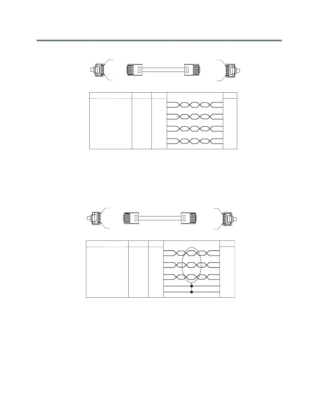
Shielded Conference Link Crossover Cable
The following diagram shows the typical shielded Polycom Conference Link crossover cable. This cable
style is appropriate for lengths longer than 25 ft.
Notice that pins 1 and 2 are mapped to pins 5 and 6, respectively, at the other end of the connector. The pin
4 wire is not used, and the shield is connected to pin 3.
If you have difficulty tying the shield train to pin 3 of the RJ-45 connector, try connecting the blue/white wire
from pin 3 to pin 3, then tie the shield drain wire to the metal case of the RJ-45 connector.
Make sure you are using the right type of RJ-45 connectors: Piercing for stranded-core cable; tulip for
solid-core cable. (Note: “Universal” connectors are not always reliable.)
COLOR P2
1
8
P1 P2
8
1
WHITE/GREEN
GREEN
WHITE/BLUE
BLUE
WHITE/ORANGE
ORANGE
WHITE/BROWN
BROWN
AWG
24
24
24
24
24
24
24
24
P1
1
2
3
4
5
6
7
8
5
6
3
4
1
2
7
8
COLOR P2
1
8
P1 P2
8
1
WHITE/GREEN
GREEN
WHITE/BLUE
BLUE
WHITE/ORANGE
ORANGE
WHITE/BROWN
BROWN
AWG
24
24
24
24
24
24
24
24
P1
1
2
3
4
5
6
7
8
5
6
3
4
1
2
7
8
COLOR P2
1
8
P1 P2
8
1
WHITE/GREEN
GREEN
WHITE/ORANGE
ORANGE
WHITE/BROWN
BROWN
DRAIN WIRE
SHIELD
AWG
24
24
24
24
24
24
24
P1
1
2
5
6
7
8
3
5
6
1
2
7
8
3
SHELL SHELL
 Loading...