Cables
Polycom, Inc. 98
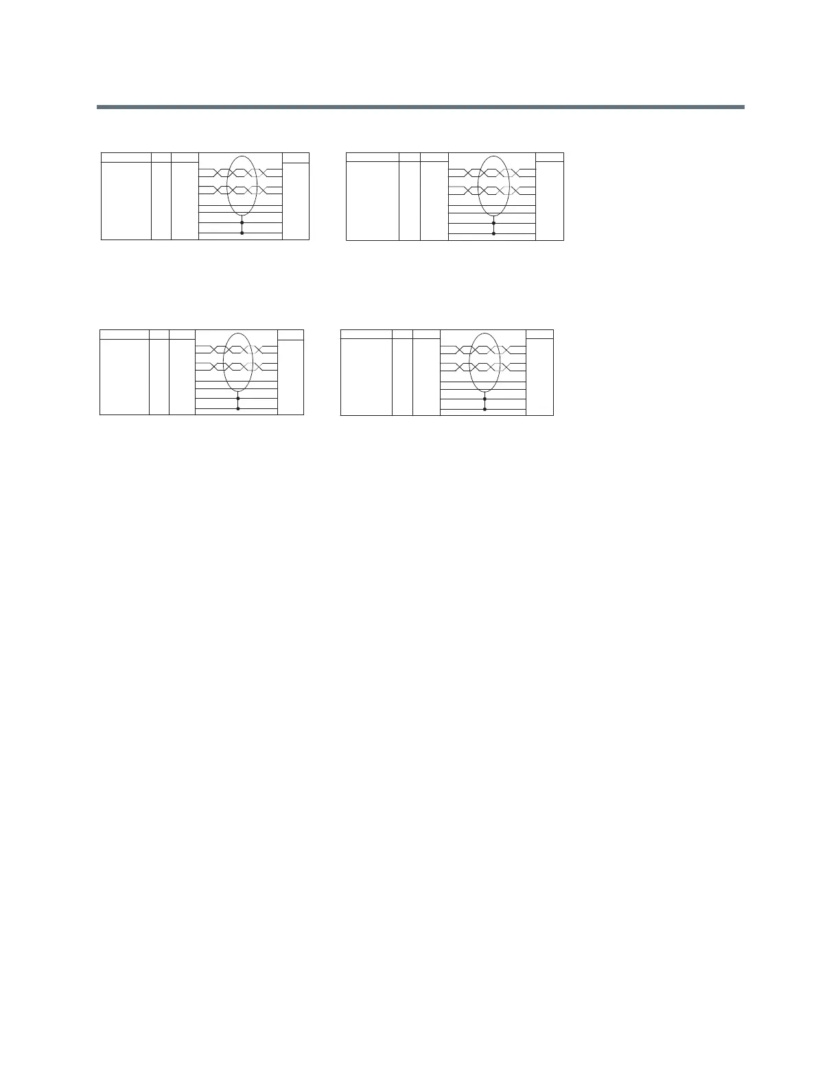
4 If you cut off P1, re-terminate the cable with an RJ-45 8-pin plug using the following tables, then
continue with step 5.
5 Whether you re-terminated the P1 or P2 end of the cable, at this point the cable can be connected
directly to the system and to the first microphone. If it is necessary to install an extension to the
system’s microphone array cable connection on a wall plate or panel, create a custom pinout cable
using shielded CAT5 cable. The cable is terminated on one end to either a shielded CAT5 keystone
jack or, if using a shielded panel coupler, a shielded RJ-45 plug connector. The other end terminates
to a Walta connector that connects to the RealPresence Group system.
P1 - Walta Electronics, M30-558-0051
P2 - RJ-45 shielded plug, Tyco 5-569552 or equivalent
P1
10
14
2
6
13
9
3
SHELL
P2
5
6
1
2
7
8
3
SHELL
AWG
28
28
28
28
24
24
COLOR
RED
ORANGE
YELLOW
GREEN
WHITE
BLACK
DRAIN WIRE
SHIELD
P1
10
14
2
6
13
9
3
SHELL
P2
5
6
1
2
7
8
3
SHELL
AWG
28
28
28
28
24
24
COLOR
BLUE
YELLOW
ORANGE
GREEN
BLACK
WHITE
DRAIN WIRE
SHIELD
VENDOR 1, P1
VENDOR 2, P1
P1 - Walta Electronics, M30-558-0051
P2 - RJ-45 shielded plug, Tyco 5-569552 or equivalent
P1- RJ-45 shielded plug, Tyco 5-569552 or equivalent
P2 - Walta Electronics, M30-558-0051
P1- RJ-45 shielded plug, Tyco 5-569552 or equivalent
P2 - Walta Electronics, M30-558-0051
P1
1
2
5
6
7
8
3
SHELL
P2
2
6
10
14
13
9
3
SHELL
AWG
28
28
28
28
24
24
COLOR
RED
ORANGE
YELLOW
GREEN
WHITE
BLACK
DRAIN WIRE
SHIELD
P1
1
2
5
6
7
8
3
SHELL
P2
2
6
10
14
13
9
3
SHELL
AWG
28
28
28
28
24
24
COLOR
BLUE
YELLOW
ORANGE
GREEN
BLACK
WHITE
DRAIN WIRE
SHIELD
VENDOR 1
VENDOR 2
 Loading...