Measurements and Results
R&S
®
FSVA3000/ R&S
®
FSV3000
287User Manual 1178.8520.02 ─ 01
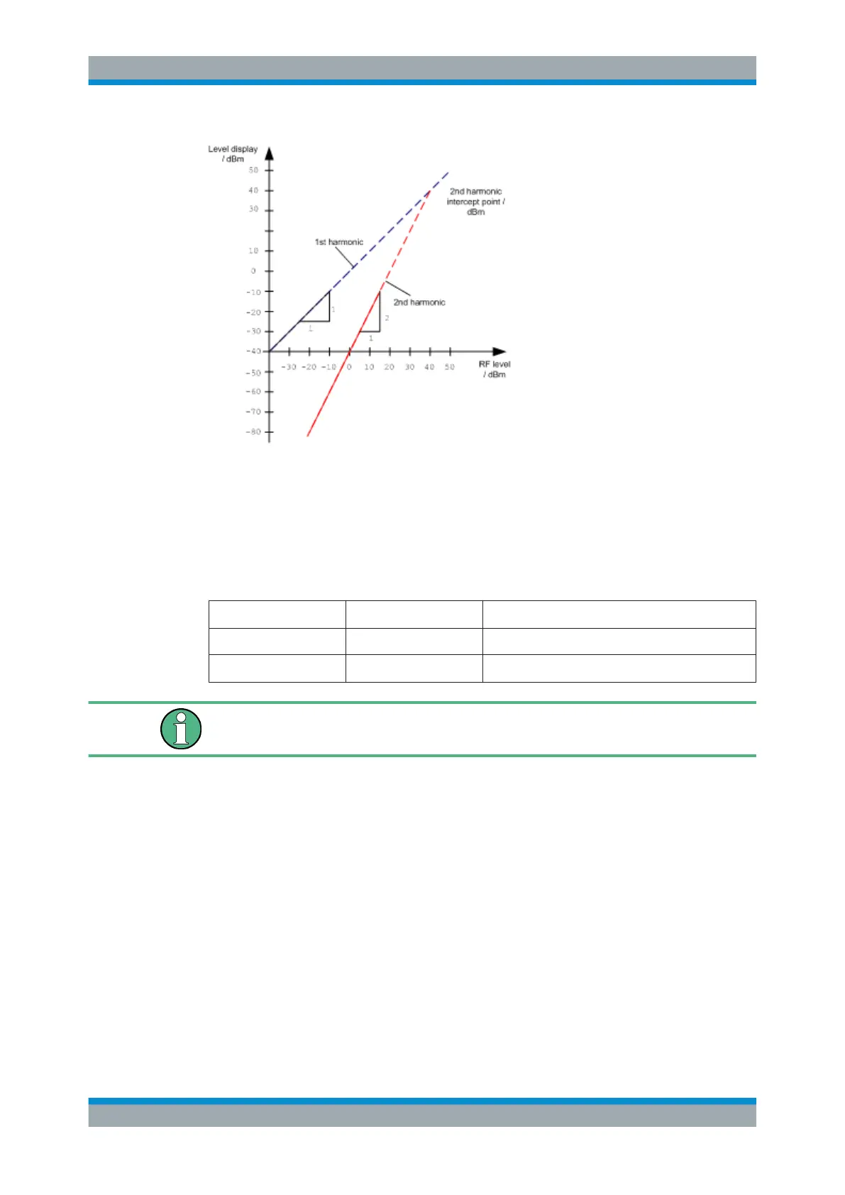
Figure 7-44: Extrapolation of the 1st and 2nd harmonics to the 2nd harmonic intercept at 40 dBm
The following formula for the obtainable harmonic distortion d
2
in dB is derived from the
straight-line equations and the given intercept point:
d
2
= S.H.I – P
I
(1)
where:
d
2
= harmonic distortion
S.H.I. = second harmonic intercept
P
I
= mixer level/dBm
The mixer level is the RF level applied to the RF input minus the set RF attenuation.
The formula for the internally generated level P
1
at the 2
nd
harmonic in dBm is:
P
1
= 2 * P
I
– S.H.I. (2)
The lower measurement limit for the harmonic is the noise floor of the signal analyzer.
The harmonic of the measured DUT should – if sufficiently averaged by means of a
video filter – be at least 4 dB above the noise floor so that the measurement error due
to the input noise is less than 1 dB.
Rules for measuring high harmonic ratios
The following rules for measuring high harmonic ratios can be derived:
●
Select the smallest possible IF bandwidth for a minimal noise floor.
●
Select an RF attenuation which is high enough to measure the harmonic ratio only.
Harmonic Distortion Measurement

 Loading...


