Getting Started
R&S
®
FSVA3000/ R&S
®
FSV3000
53User Manual 1178.8520.02 ─ 01
5.2.1.15 RF Input 50 Ohm
Connect a device under test (DUT) to the R&S FSV/A to provide RF input which is then
analyzed in an RF measurement. Connect the DUT to the "RF Input" on the
R&S FSV/A via a cable equipped with an appropriate connector.
Risk of instrument damage
Do not overload the input. For maximum allowed values, see the data sheet. A DC
input voltage (for AC coupling) of 50 V must never be exceeded. For DC coupling, DC
input voltage is not allowed.
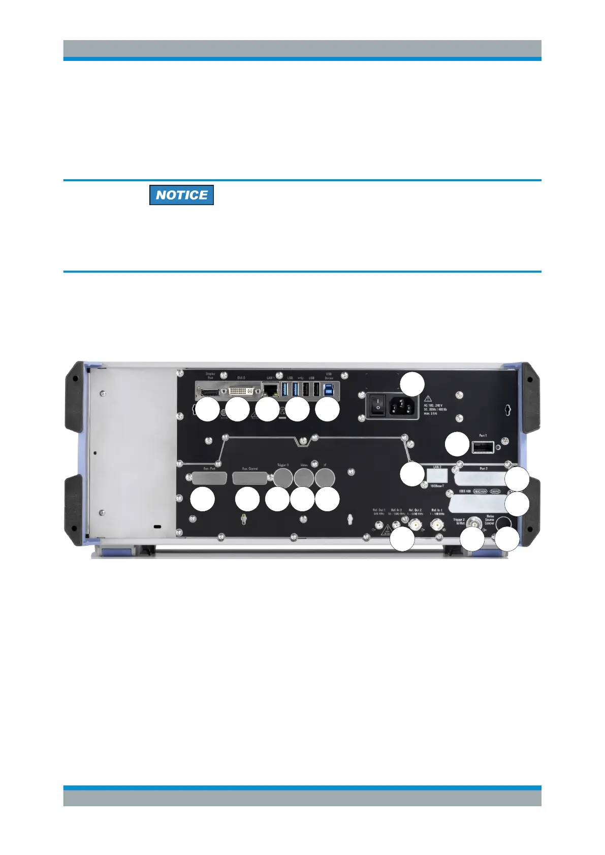
5.2.2 Rear Panel View
This figure shows the rear panel view of the R&S FSV/A. The individual elements are
described in more detail in the subsequent sections.
1
2 6
12
7
3 5
14
13
8 11
16 17
15
18
109
4
Figure 5-3: Rear panel view
1 = AC Power Supply Connection and Main Power Switch
2 = Display Port for external display (requires R&S FSV3-B114)
3 = DVI connector for external display
4 = LAN 1 connector
5+6 = USB (Device) connectors (device connector requires R&S FSV3-B114)
7 = Aux. Port (requires option R&S FSV3-B5)
8 = Aux. Control connector (requires option R&S FSV3-B5)
9 = Trigger 3 (output) connector (requires option R&S FSV3-B5)
10 = Video output connector (requires option R&S FSV3-B5)
11 = IF output connector (requires option R&S FSV3-B5)
12 = Port 1 connector
13 = LAN 2 (10GBase-T) connector (requires option R&S FSV3-B6)
14 = reserved for future use
15 = IEEE 488/ IEC625/ SCPI (GPIB) interface (requires option R&S FSV3-B5)
Instrument Tour

 Loading...


