Measurements and Results
R&S
®
FSVA3000/ R&S
®
FSV3000
299User Manual 1178.8520.02 ─ 01
The calculated TOI is indicated in the marker information. The markers required for
calculation are displayed in the marker table.
4. If the signal changes significantly during or after the TOI measurement, use the
"Search Signals" function to start a new signal search automatically and restart the
calculation of the TOI.
7.11.6 Measurement Example – Measuring the R&S FSV/A's Intrinsic Inter-
modulation
A programming example demonstrating a TOI measurement in a remote environment
is provided in Chapter 14.5.11.2, "Programming Example: Measuring the TOI",
on page 863.
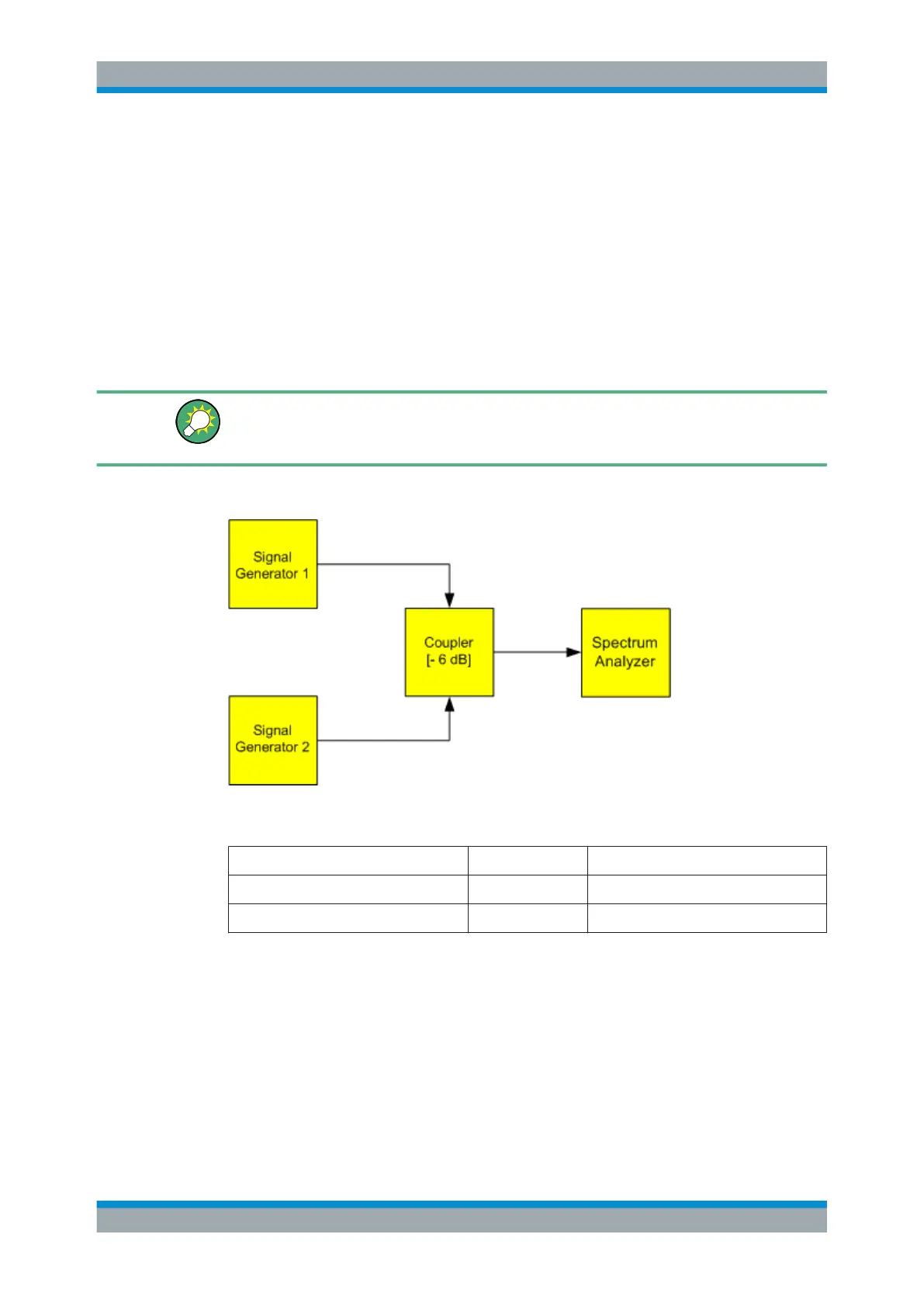
Test setup:
Signal generator settings (e.g. R&S SMW):
Device Level Frequency
Signal generator 1 -4 dBm 799.6 MHz
Signal generator 2 -4 dBm 800.4 MHz
Setting up the measurement
1. Preset the R&S FSV/A.
2. Set the center frequency to 800 MHz and the frequency span to 3 MHz.
3. Set the reference level to -10 dBm and RF attenuation to 0 dB.
4. Set the resolution bandwidth to 10 kHz.
The noise is reduced, the trace is smoothed further and the intermodulation prod-
ucts can be seen clearly.
Third Order Intercept (TOI) Measurement

 Loading...


