Common Measurement Settings
R&S
®
FSVA3000/ R&S
®
FSV3000
310User Manual 1178.8520.02 ─ 01
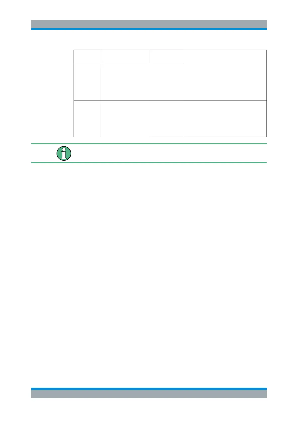
MultiMode
setting
Offset compensation Offset compen-
sation range
Application
P-Mode DC voltage at positive
input terminal
±24 V Measurement of single-ended AC signals
with high superimposed DC component at
the positive input terminal.
Note: The maximum voltage difference
between the positive and negative input ter-
minals is 16 V.
N-Mode DC voltage at negative
input terminal
±24 V Measurement of single ended AC signals
with high superimposed DC component at
the negative input terminal.
Note: The maximum voltage difference
between the positive and negative input ter-
minals is 16 V.
If the offset for DM-mode or CM-mode is changed, the offsets for the P-mode and N-
mode are adapted accordingly, and vice versa.
8.2.1.2 Receiving and Providing Trigger Signals
Using one of the "Trigger Input / Output" connectors of the R&S FSV/A, the
R&S FSV/A can use a signal from an external device as a trigger to capture data.
Alternatively, the internal trigger signal used by the R&S FSV/A can be output for use
by other connected devices. Using the same trigger on several devices is useful to
synchronize the transmitted and received signals within a measurement.
For details on the connectors see the R&S FSV/A "Getting Started" manual.
External trigger as input
If the trigger signal for the R&S FSV/A is provided by an external device, the trigger
signal source must be connected to the R&S FSV/A and the trigger source must be
defined as "External" in the R&S FSV/A.
Trigger output
The R&S FSV/A can provide output to another device either to pass on the internal
trigger signal, or to indicate that the R&S FSV/A itself is ready to trigger.
The trigger signal can be output by the R&S FSV/A automatically, or manually by the
user. If it is provided automatically, a high signal is output when the R&S FSV/A has
triggered due to a sweep start ( "Device Triggered" ), or when the R&S FSV/A is ready
to receive a trigger signal after a sweep start ( "Trigger Armed" ).
Manual triggering
If the trigger output signal is initiated manually, the length and level (high/low) of the
trigger pulse is also user-definable. Note, however, that the trigger pulse level is always
opposite to the constant signal level defined by the output "Level" setting, e.g. for
"Level" = "High", a constant high signal is output to the connector until the "Send Trig-
ger" button is selected. Then, a low pulse is provided.
Data Input and Output

 Loading...


