40 Rockwell Automation Publication KNX-SG001H-EN-P - December 2020
Kinetix 5700 Servo Drives
DC-bus Power Supply Input Power Configurations
A single 2198-Pxxx DC-bus (converter) power supply can supply the Kinetix 5700 drive system with 276…747V shared DC-bus power
(3.5…46 kW). For additional output power (kW) you can install two or three 2198-P208 DC-bus power supplies. You can also extend the DC-bus
to additional inverter clusters via accessory modules.
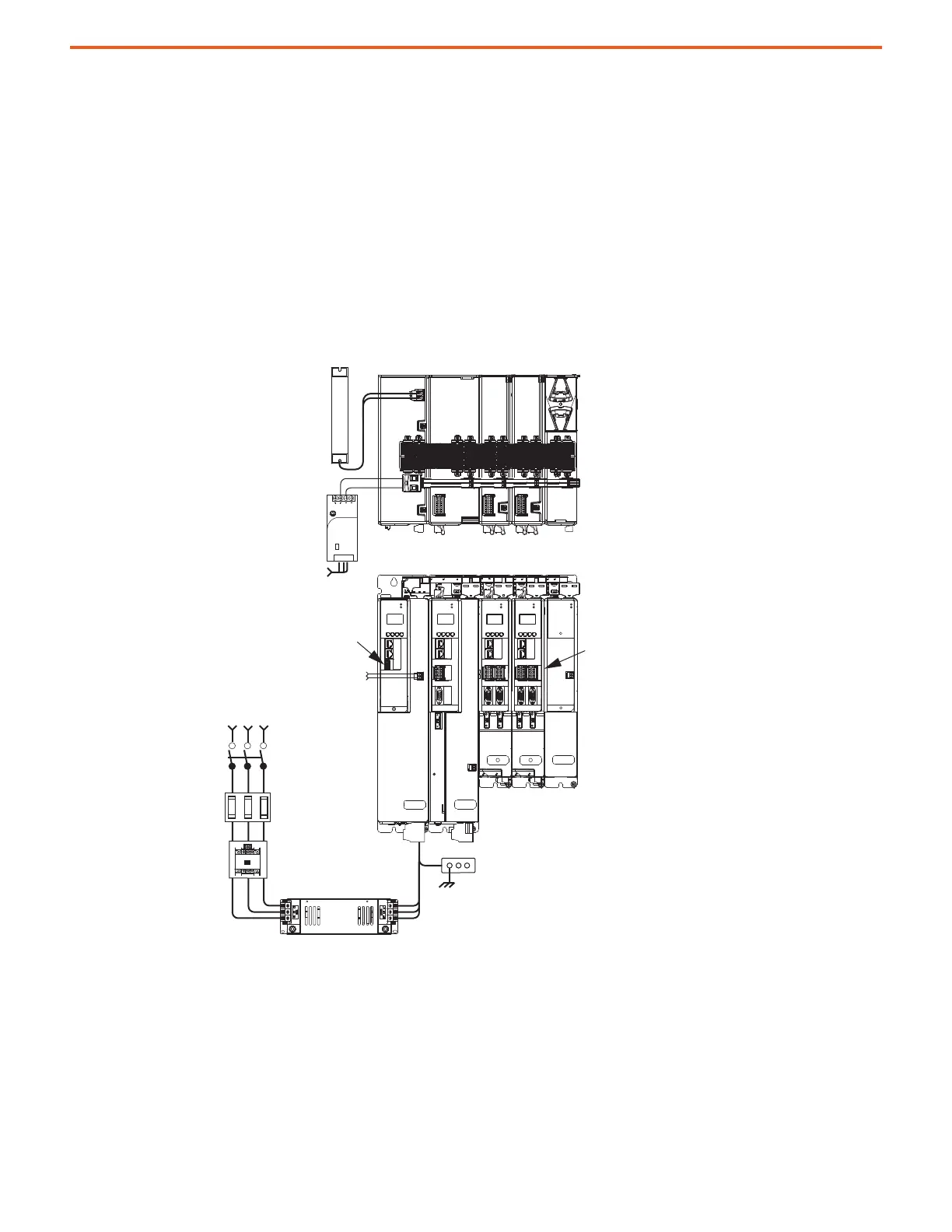
DC-bus Power Supply Configuration Example
In this multi-axis example, AC input power is fed to the DC-bus (converter) power supply. One single-axis (inverter) module and two dual-axis
(inverter) modules support five axes of motion. The DC-bus power supply is mounted on the far left and the inverters are positioned on the
right, but the reverse mounting order (right to left) is also possible.
Digital inputs are wired to sensors and the control circuitry at the IOD connectors. The contactor-enable relay protects the DC-bus power
supply in the event of shutdown fault conditions.
1606-XL
Power Supply
Input
Allen-Bradley
MOD
NET
MOD
NET
MOD
NET
MOD
NET
2
1
1
1
4
I/O
I/O
6
5
10
2
1
2
1
2
1
1
I/O-A
6
510
1
I/O-B
6
510
UFB
UFB-A UFB-B
UFB-A UFB-B
D+
D-
D+
D-
D+
D-
MF-A MF-B MF-A MF-B
D+
D-
MBRK
+
-
DC+
SH
MOD
DC BUS
D+
D-
MF
MODULE
STATUS
SB+/NC
NC
19
8
16
19
8
16
19
8
16
1
I/O-A
6
510
1
I/O-B
6
510
S1A
SCA
S2A
SB-
NC
NC
SB+/NC
NC
S1A
SCA
S2A
SB-
NC
NC
SB+/NC
NC
S1A
SCA
S2A
SB-
NC
NC
Bulletin 2198
Shunt Module
(optional component)
Magnetic Contactor (M1) Control String
1606-XLxxx
24V DC Control, Digital Inputs,
and Motor Brake Power (customer-supplied)
AC Input Power
Kinetix 5700 Servo Drive System
(front view)
Shared-bus connection system for
DC-bus and 24V DC control power.
Kinetix 5700 Servo Drive System
(top view)
Line Disconnect
Device
195…528V AC
Three-phase Input Power
Circuit
Protection
Magnetic (M1)
Contactor
Bonded Cabinet
Ground Bus
2198-DBRxx-F
AC Line Filter
(required for CE)
Converter Digital Inputs
Inverter Digital Inputs
Shared DC (DC bus) Power
Shared 24V Control Power
(24V shared-bus connection system is optional)
DC-bus
Power
Single-axis
Inverter
Dual-axis
Inverters
Capacitor
Module

 Loading...


