4.21
Date Code 20150130 Instruction Manual SEL-787 Relay
Protection and Logic Functions
Basic Protection
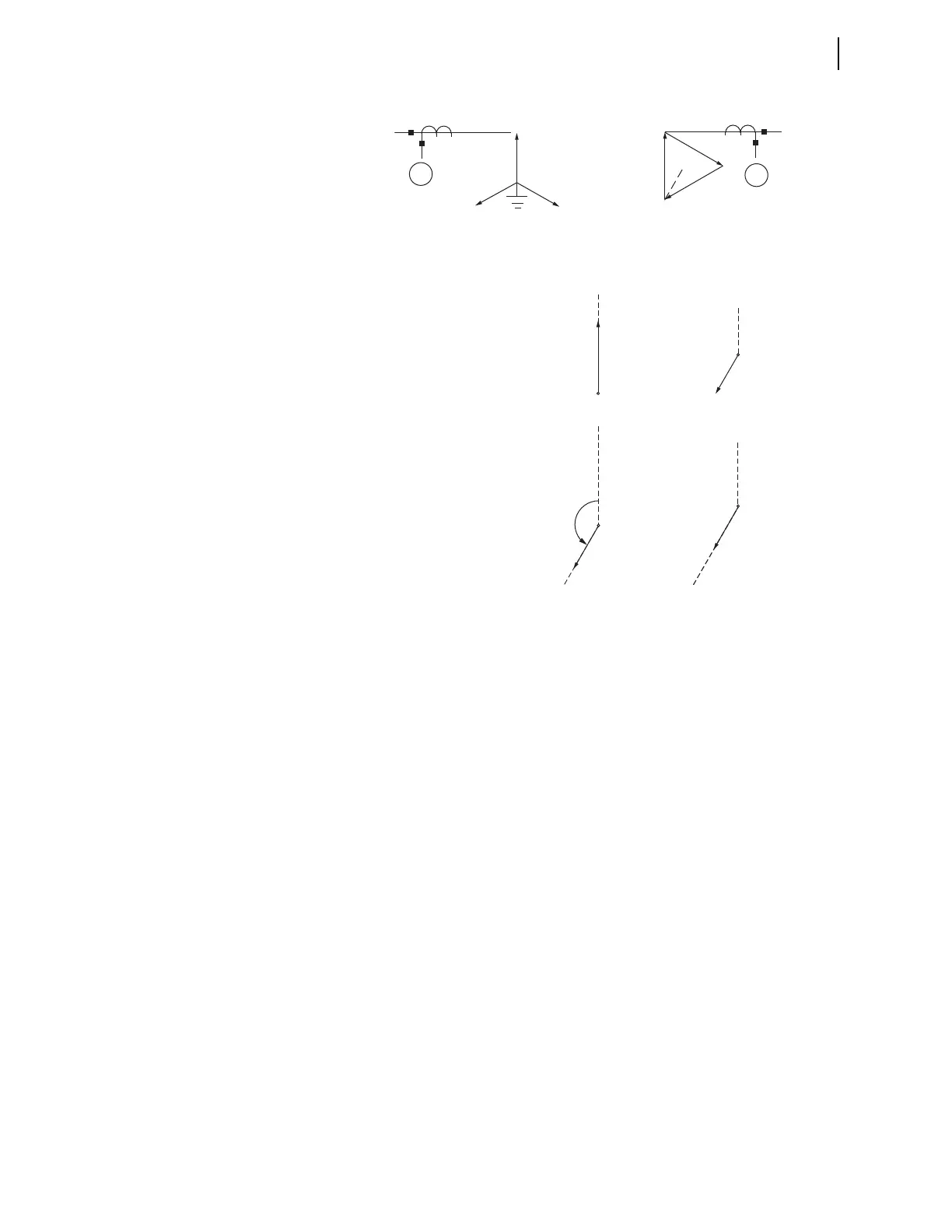
Figure 4.9 Example 2 for WnCTC Selection
Step 4. Select values of WnCTC for each winding.
We have selected W2CTC = 0 as the setting for Winding 2, the
reference winding. Beginning with Winding 1 at “noon,” adjust
the Winding 1 position in the CCW direction until arrival at the
“7 o’clock” reference direction. This procedure requires five
30-degree increments, or five “hours” of adjustment. Thus, we
choose W1CTC = 5 as the setting.
Step 5. Ensure that there will be no wye windings with wye CTs and a
setting of WnCTC = 0. In this case, the primary winding is
wye-connected and has wye-connected CTs.
In Step 4, because we chose the delta winding as reference, we
were able to set W2CTC at zero. This allowed the wye winding
to be delta compensated using Matrix 5.
The process is now complete. The relay receives the two
settings as W1CTC = 5 and W2CTC = 0.
Preferred Compensation Settings
The review presented previously primarily explains the flexibility the relay
offers in selecting the WnCTC settings for your application. Although the
relay offers flexibility, a few WnCTC settings are preferred over others. This
sub-section reviews the preferred WnCTC settings for different transformer
connections. Refer to Table 4.5 for the preferred compensation settings that
provide better security over the other combinations for external faults.
Although these are preferred settings, if your application requires a different
Y
1
115 kV
A
B
C
34.5 kV
2
B
C
A
Y
(DAB)
Yd7 Connection (ABC Rotation)
A
A
Xfmr
Phase
Relationship
Xfmr + CT
Phase
Relationship
CTComp: W1CTC = 5 W2CTC = 0
Terminal A
A
(REF.)
(REF.)
W1CTC
(Winding 2)(Winding 1)



 To Next Page