neutral position. The setting units are kilovolts.
Relay
Winding 1
Relay
Winding 2
WYE CT
500:5
I
W1
A
B
C
a
b
c
Winding 1 (69 kV) Winding 2 (13.8 kV)
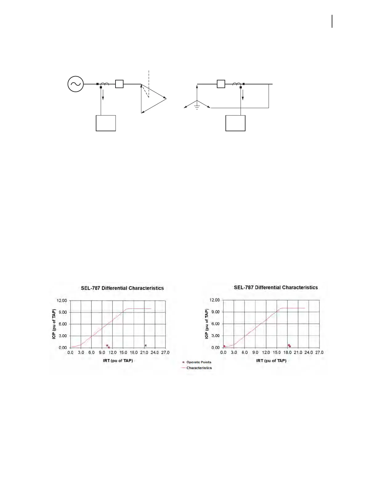
Delta (DY1)–Wye Transformer
WYE CT
2500:5
X A-B Fault
Common Settings for Case 1 and Case 2
VWDG1 = 69 MVA = 50 O87P = 0.30 SLP1 = 25 TAP1 = 4.18
VWDG2 = 13.8 IRS1 = 3.0 U87P = 10.0 SLP2 = 70 TAP2 = 4.18
IAW1 = 4600 ∠180.0° IAW2 = 20000 ∠0.0°
IBW1 = 2300 ∠0.0° IBW2 = 20000 ∠180.0°
ICW1 = 2300 ∠0.0° ICW2 = 0 ∠0.0°
IAW1 = 46.0 ∠180.0° IAW2 = 36.0 ∠0.0°
IBW1 = 23.0 ∠0.0° IBW2 = 40.0 ∠180.0°
ICW1 = 23.0 ∠0.0° ICW2 = 0.0 ∠0.0°
Case 1 (Preferred Compensation Settings) Case 2 (Other Compensation Settings)
W1CTC = 0, W2CTC = 1 W1CTC = 11, W2CTC = 12
I1W1C = 11.00 ∠180.00° I1W2C = 10.50 ∠0.00° I1W1C = 9.52 ∠180.00° I1W2C = 8.93 ∠0.00°
I2W1C = 5.50 ∠0.00° I2W2C = 5.50 ∠180.00° I2W1C = 9.52 ∠0.00° I2W2C = 9.24 ∠180.00°
I3W1C = 5.50 ∠0.00° I3W2C = 4.97 ∠180.00° I3W1C = 0.00 ∠0.00° I3W2C = 0.31 ∠0.00°
IOP1 = 0.51 IRT1 = 21.48 IOP1 = 0.59 IRT1 = 18.45
IOP2 = 0.02 IRT2 = 11.01 IOP2 = 0.28 IRT2 = 18.76
IOP3 = 0.52 IRT3 = 10.47 IOP3 = 0.31 IRT3 = 0.31
Secondary Currents Before
Compensation in Amperes
Secondary Currents After
Compensation in Per Unit of
the TAP Setting
Restraint/Operate Currents
in Per Unit of the TAP
Setting
Primary Currents
in Amperes
50 MVA
I
W2
87 Element Settings
 Loading...


