4.58
SEL-787 Relay Instruction Manual Date Code 20150130
Protection and Logic Functions
Voltage-Based Protection
Power Elements
You can enable as many as two independent three-phase power elements in the
SEL-787 relay. Each enabled element can be set to detect real power or
reactive power. When voltage inputs to the relay are from delta connected PTs
or when single voltage input is used, the relay cannot account for unbalance in
the voltages in calculating the power. Take this into consideration in applying
the power elements.
With
SELOGIC control equations, the power elements provide a wide variety of
protection and control applications. Typical applications are:
➤ Overpower and/or underpower protection/control
➤ Reverse power protection/control
➤ VAR control for capacitor banks
EPWR := 3P1 enables one three-phase power element. Set EPWR := 3P2 if
you want to use both elements.
Set the element pickup, 3PH PWR ELEM PU to desired values in secondary
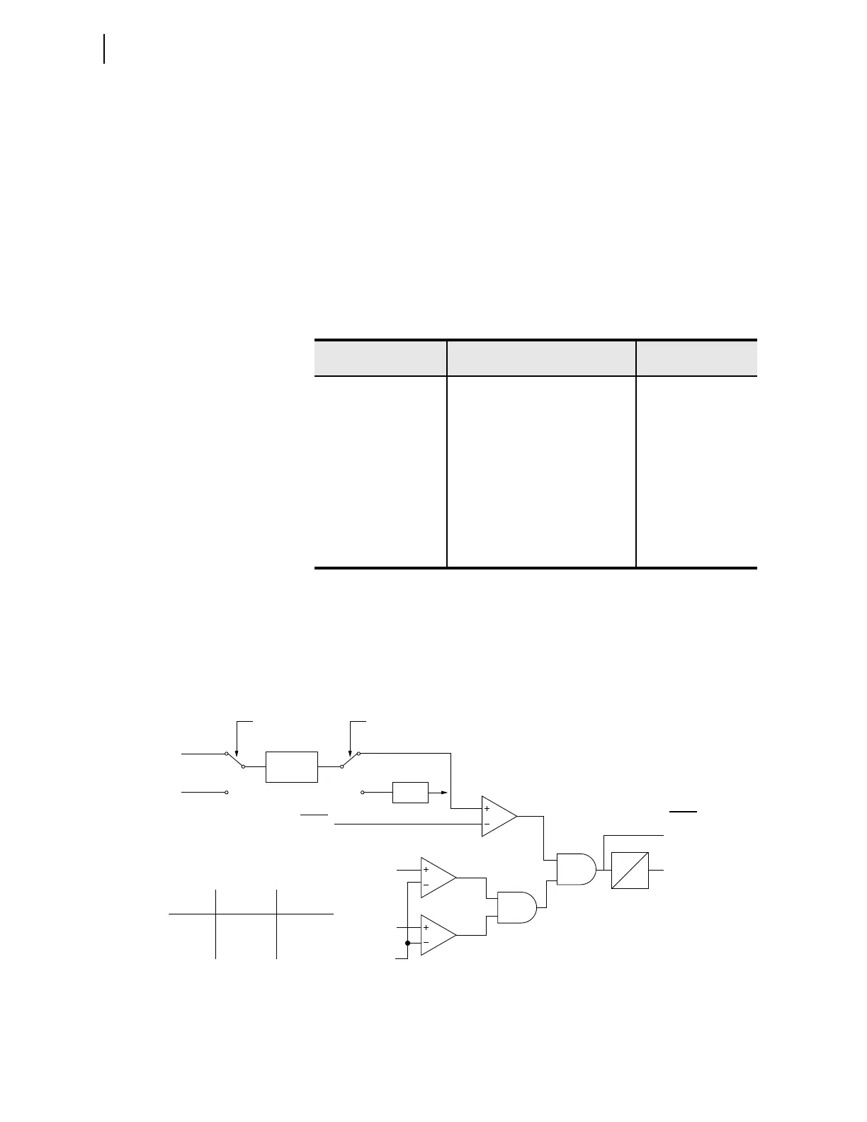
VA units. Figure 4.43 shows the power element logic diagram and Figure 4.44
shows the operation in the Real/Reactive power plane.
Figure 4.43 Three-Phase Power Elements Logic
Table 4.23 Power Element Settings
Setting Prompt Setting Range
Setting Name :=
Factory Default
ENABLE PWR ELEM N, 3P1, 3P2 EPWR := N
3PH PWR ELEM PU OFF, 1.0–6500.0 VA (secondary)
a
a
The range shown is for 5 A input; range for 1 A input is OFF, 0.2—1300.0 VA.
3PWR1P := OFF
PWR ELEM TYPE +WATTS, –WATTS, +VARS, –
VA RS
PWR1T := +VARS
PWR ELEM DELAY 0.0–240.0 sec PWR1D := 0.0
3PH PWR ELEM PU OFF, 1.0–6500.0 VA (secondary)
a
3PWR2P := OFF
PWR ELEM TYPE +WATTS, –WATTS, +VARS, –
VA RS
PWR2T := +VARS
PWR ELEM DELAY 0.0–240.0 sec PWR2D := 0.0
PWRnD
0
3PWRnP
|V
AB
|
20 V
3PWRnT
Relay
Word
Bits
Switch A
Position
+WATTS
–WATTS
+VARS
–VARS
Setting
PWRnT
1
1
2
2
Switch B
Position
1
2
1
2
Where n = 1 or 2
2 Cycle
Average
•(–1)
Switch A Switch B
11
22
3PWRnP
|V
BC
|
Setting
P
Q