4.50
SEL-787 Relay Instruction Manual Date Code 20150130
Protection and Logic Functions
Voltage-Based Protection
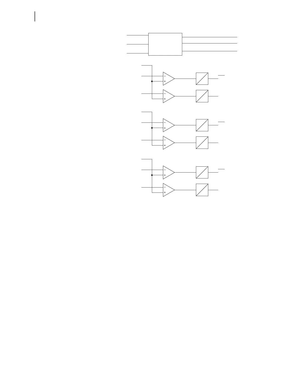
Figure 4.36 Overvoltage Element Logic
Volts Per Hertz
Elements
Overexcitation occurs when a transformer magnetic core becomes saturated.
When this happens, stray flux is induced in nonlaminated components,
causing overheating. In the SEL-787 Relay a volts/hertz element detects
overexcitation. The SEL-787 provides a sensitive definite time volts/hertz
element, plus a tripping element with a composite operating time. The relay
calculates the present transformer volts/hertz as a percent of nominal, based
on the present and nominal voltages and frequencies. The settings VNOM and
FNOM define the nominal transformer voltage and frequency, respectively.
Figure 4.37 shows a logic diagram of the volts/hertz elements. If the torque-
control 24TC SEL
OGIC control equation is true and the present volts/hertz
exceed the 24D1P setting, the relay asserts the 24D1 Relay Word bit and starts
the 24D1D timer. If the condition remains for 24D1D seconds, the relay
asserts the 24D1T Relay Word bit. Typically, you should apply this element as
an overexcitation alarm.
59P1P
|VP|
59P1D
0
59P1T
When DELTA_Y := WYE
When DELTA_Y := DELTA
59P2P
59P2D
0
59P2T
59P1D
0
59P1T
59P2D
0
59P2T
Relay
Word
Bits
59P1P
|VPP|
59P2P
Relay
Word
Bits
VAB or VA
VBC or VB
VCA or VC
Voltage
Magnitude
Calculation
|VP|
|VPP|
(Maximum Phase Voltage Magnitude)
|3V2|
(Negative Sequence Voltage Magnitude)
(Maximum Phase-to-Phase Voltage Magnitude)
59P1P, 59P2P, 59Q1P, 59Q2P = Settings
59Q1P
|3V2|
59Q1D
0
59Q1T
When DELTA_Y := WYE or DELTA
59Q2P
59Q2D
0
59Q2T
Relay
Word
Bits