4.10
SEL-787 Relay Instruction Manual Date Code 20150130
Protection and Logic Functions
Basic Protection
and that value is used in the relay characteristic. Consider, for example, the
simple case of Slope 1, i.e., a straight line through the origin. The general
equation for a line is:
y=m • x + c
More specifically, in the SEL-787:
IOP = SLP1 • IRT + c
Because the line starts at the origin, the value of c is normally zero. The sum
of the second- and fourth-harmonic currents now forms the constant c in the
equation, raising the relay characteristic proportionally to the harmonic values.
Harmonic Blocking
While the restrained differential elements are making decisions, a parallel
blocking decision process occurs regarding the magnitudes of specific
harmonics in the IOP quantities.
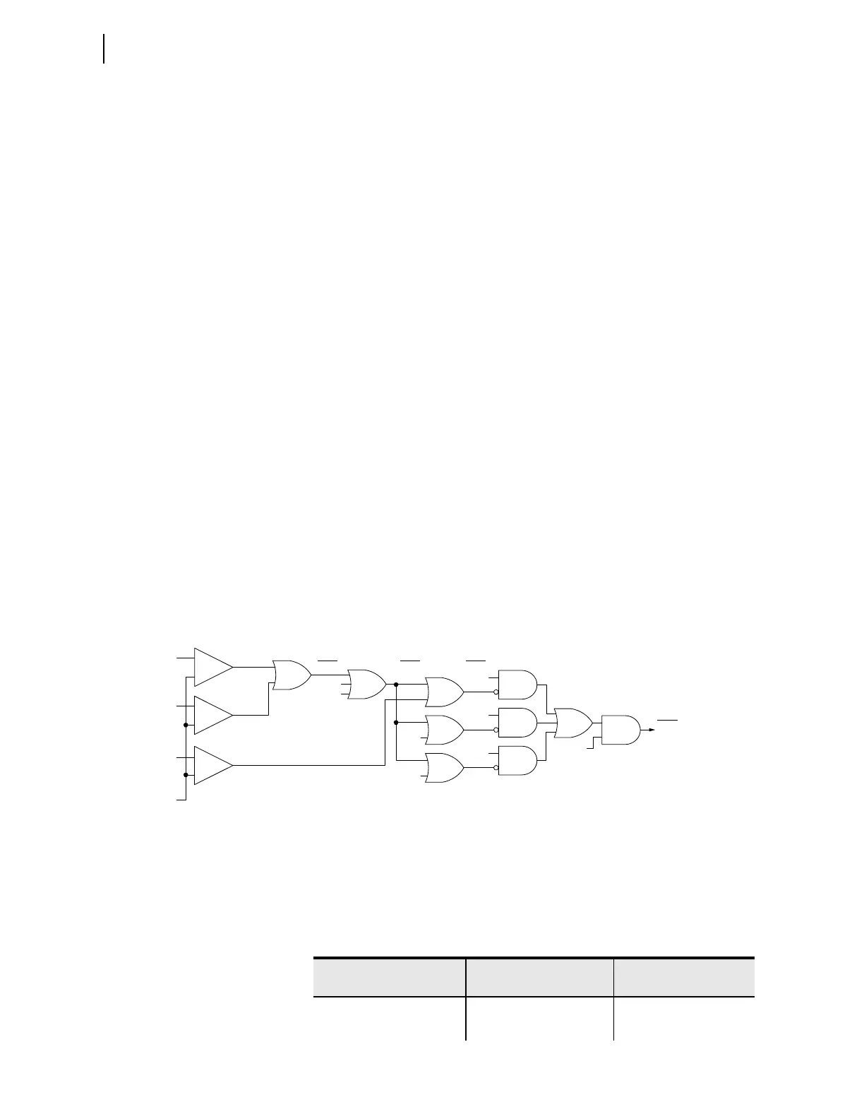
Figure 4.5 shows how blocking elements, (87BL1, 87BL2, and 87BL3)
supervise the restrained differential elements if the second-, fourth-, or fifth-
harmonic operating current is above its set threshold. The blocking prevents
improper tripping during transformer inrush or allowable overexcitation
conditions. The SEL-787 uses common (cross-phase) blocking. Common
blocking prevents all restrained elements (87Rn) from tripping if any blocking
element is picked up.
However, an independent blocking is used for the fifth-harmonic current. In
this logic, an individual element will only disable tripping of that element.
An additional alarm function for fifth harmonic to warn of overexcitation (not
shown in Figure 4.5) employs a separate threshold (TH5P) and an adjustable
timer (TH5D). This threshold and timer may be useful for transformer
applications in or near generating stations.
Figure 4.5 Differential Element Harmonic Blocking Logic
Relay Word bits 87R and 87U are high-speed elements that must trip all
breakers. The factory default assigns 87R and 87U to trip variable setting
TRXFMR. If either bit asserts, this variable asserts bit TRIPXFMR, which
drives contact OUT103. OUT103 connects to an 86 lockout device, which
trips all breakers via multiple sets of contacts.
87HB
_
+
_
+
_
+
5HB2
87R1
87BL1
87R2
87BL2
87R3
87BL3
2_4HBL
2_4HB1
5HB3
2_4HB2
2_4HB3
5HB1
5th
Harmonic
Blocking
4th
Harmonic
Blocking
2nd
Harmonic
Blocking
HBLK=Y
I1H2
I1H4
I1H5
IOP1
Relay
Word
Bits
Relay
Word
Bits
Relay
Word
Bits
Relay
Word
Bit
Table 4.4 Differential Element Settings (Sheet 1 of 2)
Setting Prompt Setting Range
Setting Name :=
Fac tory Defau lt
XFMR DIFF ENABLE Y, N E87 := Y
WDG1 CURR TAP 0.50–31.00 A
a
TAP1 := 2.09