4.92
SEL-787 Relay Instruction Manual Date Code 20150130
Protection and Logic Functions
Global Settings (SET G Command)
AC Mode Processing (AC Control Voltage)
Figure 4.66 shows IN101R from Input IN101 applied to a pickup/dropout
timer. Different from the dc mode, there are no time settings for the debounce
timer in the ac mode: the pickup time delay is fixed at 2 ms, and the dropout
time is fixed at 16 ms. Relay Word bit IN101 is the output of the debounce
timer. To select the ac mode of debounce, set IN101D = AC.
Figure 4.66 AC Mode Processing
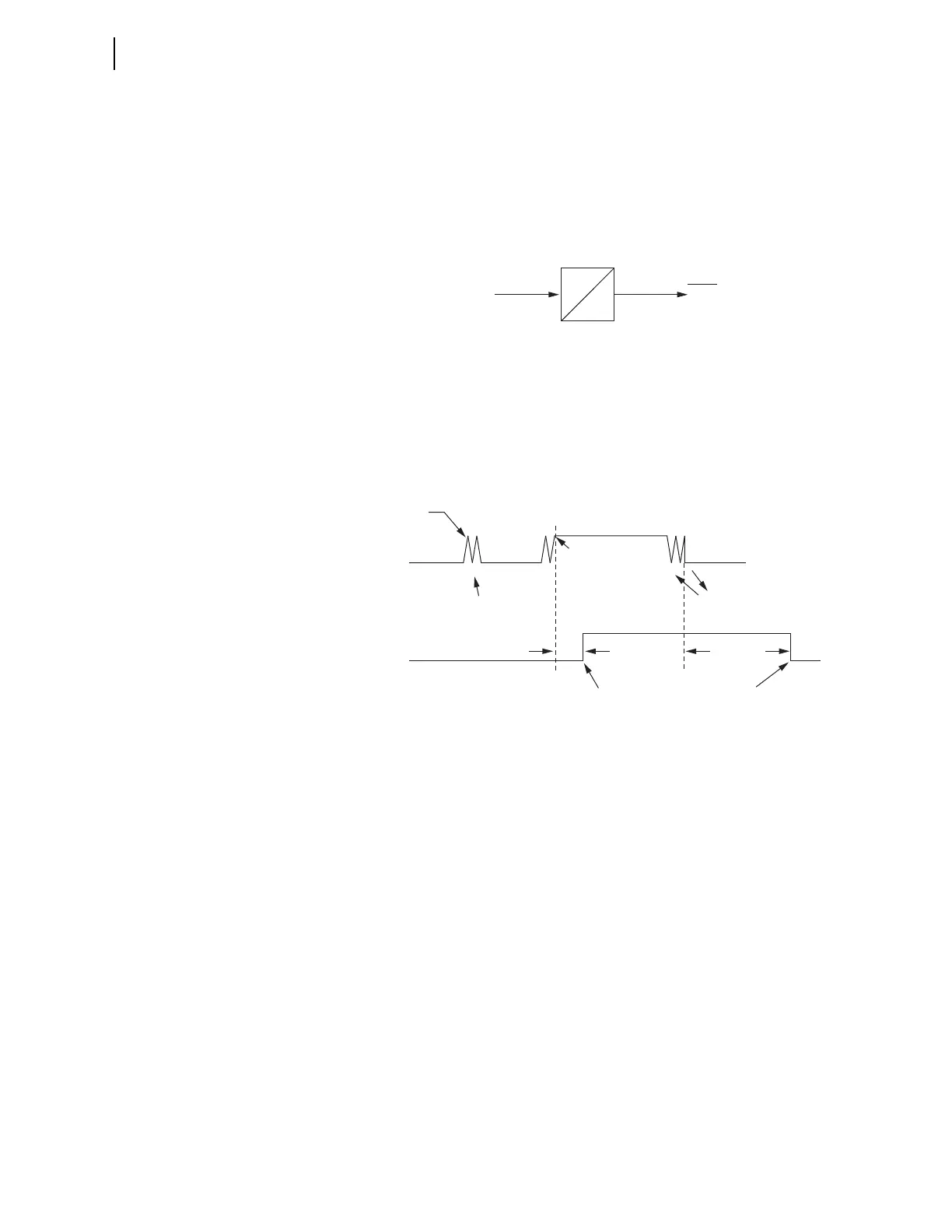
Figure 4.67 shows a timing diagram for the ac mode of operation. On the
rising edge of IN101R, the pickup timer starts timing (points marked 1 in
Figure 4.67). If IN101R deasserts (points marked 2 in Figure 4.67) before
expiration of the pickup time setting, Relay Word bit IN101 does not assert,
and remains at logical 0. If, however, IN101R remains asserted for a period
longer than the pickup timer setting, then Relay Word bit IN101 asserts to a
logical 1.
Figure 4.67 Timing Diagram for Debounce Timer Operation When Operating
in AC Mode
Deassertion follows the same logic. On the falling edge of IN101R, the
dropout timer starts timing. If IN101R remains deasserted for a period longer
than the dropout timer setting, then Relay Word bit IN101 deasserts to a
logical 0.
Table 4.42 shows the settings prompt, setting range, and factory-default
settings for a card in Slot C. See the SEL-787 Settings Sheets for a complete
list of input debounce settings.
2 ms
16 ms
IN101
Relay
Word
Bit
IN101R
Debounce Timer
IN101R
2 ms
IN101R Deasserted;
DDOT Counts
IN101R Deasserted;
DDOT Counts
Dropout Time
(16 ms)
Debounce Dropout
Timer Expires;
Relay Word Bit
IN101 Deasserts
Debounce Pickup
Timer Expires;
Relay Word Bit
IN101 Asserts
IN101R Asserted;
DPUT Counts
IN101R Asserted;
DPUT counts
Relay Word
Bit IN101
1
2
111 11
222 22
DPUT = Debounce Pickup Timer
DDOT = Debounce Dropout Timer
1 = Rising Edge: DPUT Counts
2 = Falling Edge: DDOT Counts