4.31
Date Code 20150130 Instruction Manual SEL-787 Relay
Protection and Logic Functions
Basic Protection
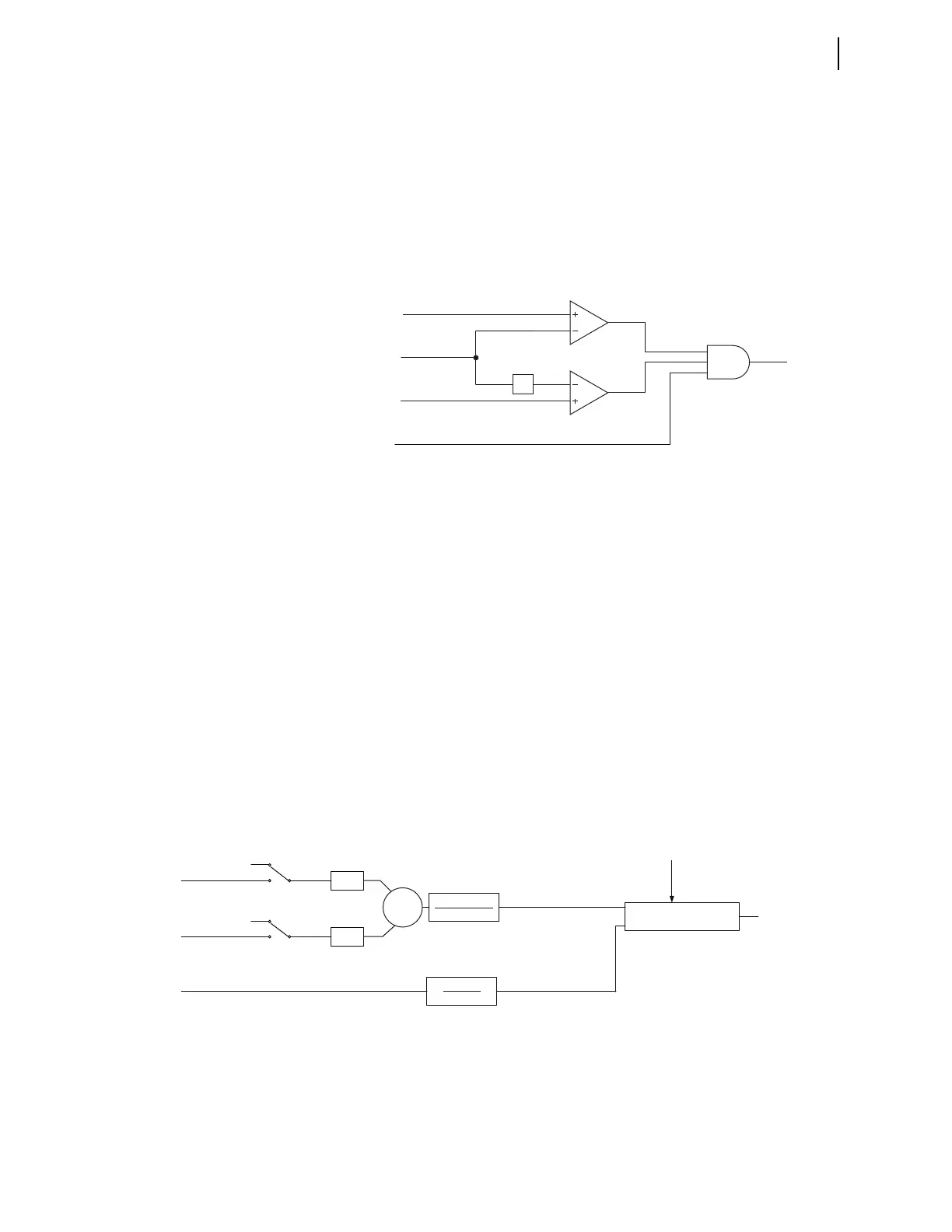
The comparator C1 compares the magnitude of the normalized IN1 value,
defined as INWPU1, against the 50REF1P setting and asserts 50NREF1 if the
measured quantity exceeds the threshold. Comparator C2 compares 0.8 of the
50REF1P setting value against the magnitude of the normalized polarizing
current, IGWPU1, and asserts 50GREF1 if the measured quantity exceeds the
threshold. The 0.8 multiplier secures the operation of the REFF1 element by
ensuring that 50GREF1 always asserts before 50NREF1. If 50NREF1,
50GREF1, and the SEL
OGIC torque control, REF1TC, all evaluate to logical 1,
then the output REF1E is asserted. When REF1E asserts, the relay enables the
logic that performs the directional calculations as shown in Figure 4.13.
Figure 4.12 REF1 Enable Logic
Figure 4.13 shows the REF1 torque control output, REFTQ1. The Switch S1
(S1a and S1b) selects the zero-sequence vector currents from the line CTs that
are part of the REF calculations as determined by the setting REF1POL. As an
example, refer to Figure 4.15. For a single-wye winding, the logic requires
one neutral CT and one set of line CTs for the REF function. If this set of line
CTs is from Terminal 1, then Switch S1a will be in Position 2, while Switch
S1b remains in Position 1. Current inputs from those terminals in Position 1
are not included in any REF element calculations. After closing the
appropriate cells of Switch S1, the relay converts the currents to primary
values by multiplying each current times the appropriate CT ratio. The relay
then sums these currents vectorially to produce the polarizing current in vector
form. To bring this value to the same base as the neutral CT, the algorithm
divides the polarizing current by the product of the neutral CT ratio and the
neutral CT nominal rating (CTRN1 • INOM1). These calculations produce
IGWPU1, the normalized polarizing current in vector form. For the operating
current, the algorithm normalizes IN1 with INOMN1 to produce INWPU1,
the normalized operating current in vector form. INOMN1 is the nominal
rating of the neutral CT, 5 A or 1 A.
Figure 4.13 REF1 Directional Element
When the algorithm meets the conditions in Figure 4.12, REF1E asserts and
enables the calculations of the directional element. To determine the direction,
the algorithm calculates the real part of the product of the polarizing quantity
and the conjugate of the operating quantity. This calculation yields the signed
|INWPU1|
(Operating Quantity)
50REF1P
(Setting)
|IGWPU1|
(Polaring Quantity)
REF1TC
(Setting)
0.8
C1
C2
50GREF1
50NREF1
AND
REF1E
IGW1
IGW2
IN1
1
CTRN1 * INOMN1
IGWPU1
(Polarizing Quantity)
1
INOMN1
INWPU1
(Operating Quantity)
Re(IGWPU1 . INWPU1*)
ENABLE
REF1E
REFTQ1
REF1 Directional Element
Σ
CTR1
CTR2
S1a
S1b
1
2
0
1
2
0
REF1POL = 1, 12
REF1POL = 2, 12