4.49
Date Code 20150130 Instruction Manual SEL-787 Relay
Protection and Logic Functions
Voltage-Based Protection
Overvoltage Function
When you connect the SEL-787 voltage inputs to phase-to-phase connected
VTs (single-phase or three-phase), as in Figure 2.17 or Figure 2.18, the relay
provides two levels of phase-to-phase overvoltage and undervoltage elements.
When you connect the SEL-787 voltage inputs to phase-to-neutral connected
VTs (single-phase or three-phase), as shown in Figure 2.17 or Figure 2.18, the
relay provides two levels of phase-to-neutral overvoltage and undervoltage
elements. The SEL-787 also includes two levels of negative-sequence
overvoltage elements. Use these elements for alarm or trip when three-phase
voltage inputs (wye or delta) are connected to the relay.
Each of the elements has an associated time delay. You can use these elements
as you choose for tripping and warning. Figure 4.35 and Figure 4.36 show the
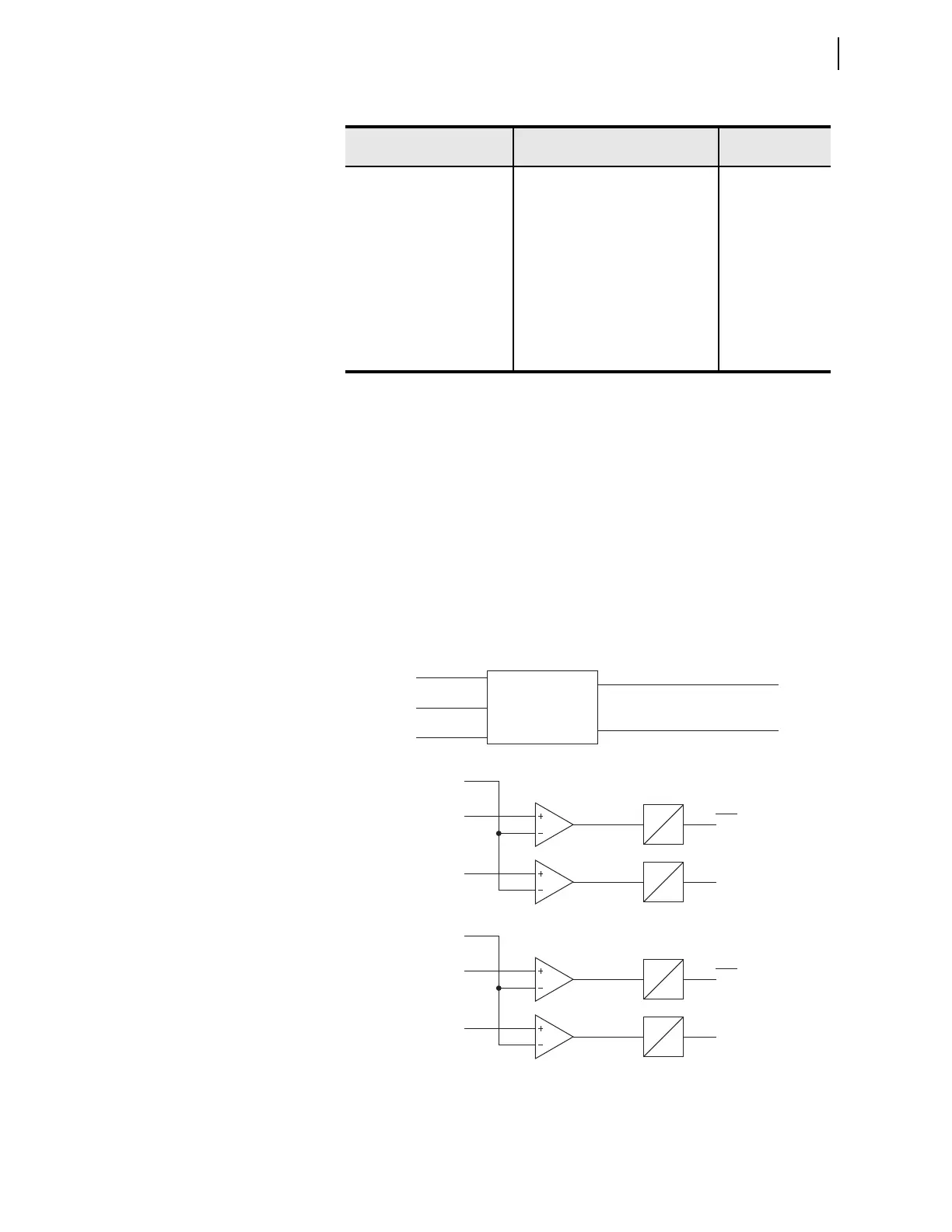
logic diagram for the undervoltage and overvoltage elements, respectively. To
disable any of these elements, set the level settings equal to OFF.
Figure 4.35 Undervoltage Element Logic
Table 4.21 Overvoltage Settings
Setting Prompt Setting Range
Setting Name :=
Fac tory Default
PHASE OV LEVEL OFF, 12.5–300.0 V 59P1P := OFF
PHASE OV DELAY 0.0–120.0 sec 59P1D := 0.5
PHASE OV LEVEL OFF, 12.5–300.0 V 59P2P := OFF
PHASE OV DELAY 0.0–120.0 sec 59P2D := 5.0
NSEQ OV LEVEL OFF, 12.5–300.0 V 59Q1P := OFF
NSEQ OV DELAY 0.0–120.0 sec 59Q1D := 0.5
NSEQ OV LEVEL OFF, 12.5–300.0 V 59Q2P := OFF
NSEQ OV DELAY 0.0–120.0 sec 59Q2D := 5.0
27P1P
|VP|
27P1D
0
27P1T
When DELTA_Y := WYE
When DELTA_Y := DELTA
27P2P
27P2D
0
27P2T
27P1D
0
27P1T
27P2D
0
27P2T
Relay
Word
Bits
27P1P
|VPP|
27P2P
Relay
Word
Bits
VAB or VA
VBC or VB
VCA or VC
Voltage
Magnitude
Calculation
|VP|
|VPP|
(Minimum Phase Voltage Magnitude)
(Minimum Phase-to-Phase Voltage Magnitude)
 Loading...


