5.15
Date Code 20150130 Instruction Manual SEL-787 Relay
Metering and Monitoring
Through-Fault Event Monitoring
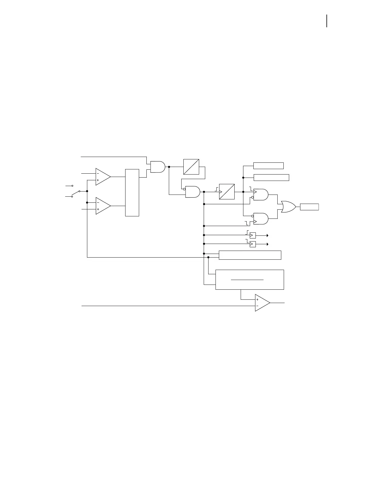
When Enable asserts, the following occurs:
➤ The thermal element advances the A-phase fault counter by
1 count.
➤ The thermal element advances the total fault counter by
1 count.
➤ The thermal element records the time when the fault starts
(rising edge of Enable).
➤ The process to determine the maximum through-fault current
for the fault duration starts.
➤ The integration process starts, whereby the element sums the
values (Equation 5.3) calculated each processing interval (1/4
of a power system cycle).
Figure 5.18 Through-Fault Diagram
The 10-cycle Timer avoids the inadvertent increment of the counters or
archiving of the data if the fault current momentarily drops below the lower
threshold level.
Setting threshold THFLTPU would usually be set to alarm for excessive,
cumulative transformer bank stress. When the integration exceeds the value as
specified by the THFLTPU setting, Relay Word bit TFLTALA asserts. Assign
output Relay Word bit TFLTALA to an output for annunciation or control
action such as to modify distribution feeder auto-reclosing (e.g., reduce the
number of reclosures from 3 to 2).
THFLTPU
ETHRFLT
(Setting)
4.75 • I
FULL LOAD
4.5 • I
FULL LOAD
IAW1
S1*
S
Q
R
0
1 min
1-minute
Timer
Enable
10-cycle
Timer
0
10
cyc
Total Counter
A-Phase Counter
Archive
Start Time
Stop Time
Maximum Current Calculation
TFLTALA
0.25
t(I
pu
) • FNOM
• 100%
1
2
Σ
IAW2
*S1 = 1 if THFLTD := 1
S1 = 2 if THFLTD := 2
 Loading...


