2.10
SEL-787 Relay Instruction Manual Date Code 20150130
Installation
I/O Configuration
I/O Card (4 DI/3 DO)
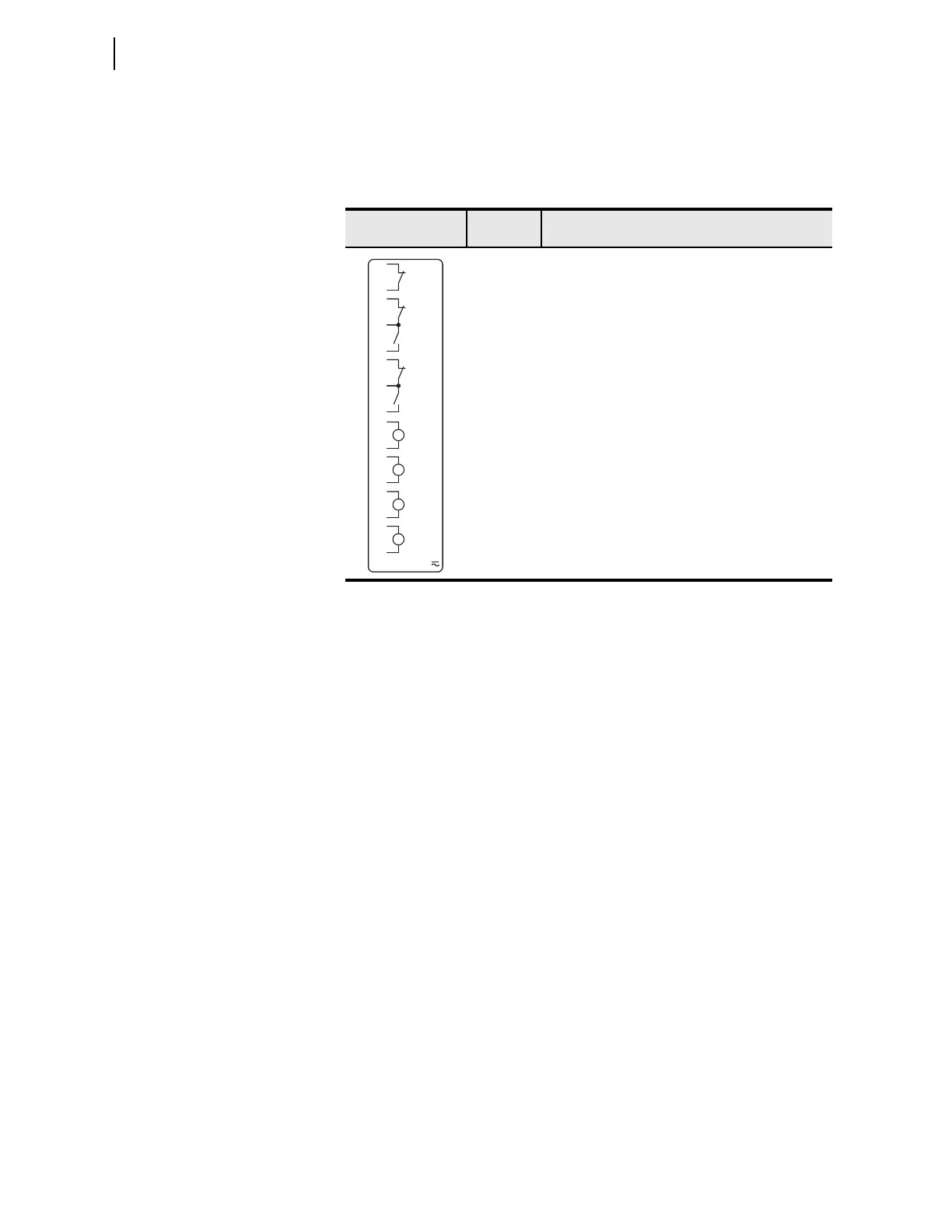
Supported in any nonbase unit slot (Slot C through Slot E), this card has four
digital inputs, one Form-B digital output (normally closed contact output) and
two form-C digital output contacts. Table 2.11 shows the terminal allocation.
Card Configuration
Procedure
Changing card positions or expanding on the initial number of cards requires
no card programming; the relay detects the new hardware and updates the
software accordingly (you still have to use the SET command to program the
I/O settings).
The SEL-787 offers flexibility in tailoring I/O to your specific application.
The SEL-787 has six rear-panel slots, labeled as Slots A, B, C, D, E, and Z.
Slots A, B, and Z are base unit slots, each associated with a specific function.
Optional digital/analog I/O cards are available for the SEL-787 in Slots C, D,
and E. Optional communications cards are available only for Slot C, an RTD
card is available only for Slot D, and 1 A/5 A CT combinations for voltage/
current cards are available only on Slots E and Z. Figure 2.2 shows the slot
allocations for the cards. Because installations differ substantially, the
SEL-787 offers a variety of card configurations that provide options for many
diverse applications. Choose the combination of cards most suited for your
application.
Swapping Optional I/O Boards
When an I/O board is moved from one slot to a different slot, the associated
settings for the slot the card is moved from will be lost. For example, if a 4 DI/
4 DO card is installed in Slot 4 (Slot D), the SEL
OGIC settings OUT401–
OUT404 would be available. If OUT401 = IN101 and 51P1T and the card is
moved to a different slot, then the OUT4xx settings will be lost. This is true for
all the digital and analog I/O cards.
Table 2.11 Four Digital Inputs, One Form-B Digital Output, Two Form-C
Digital Outputs (4 DI/3DO) Card Terminal Allocation
Side-Panel
Connections Label
Term i nal
Number
Description
a
a
x=3, 4, or 5 (e.g., OUT401, OUT402, etc. if the card was installed in Slot D).
01, 02 OUTx01, driven by OUTx01 SELOGIC
control equation
03, 04, 05 OUTx02, driven by OUTx02 SEL
OGIC
control equation
06, 07, 08 OUTx03, driven by OUTx03 SEL
OGIC
control equation
09, 10 INx01, drives INx01 element
11, 12 INx02, drives INx02 element
13, 14 INx03, drives INx03 element
15, 16 INx04, drives INx04 element
INPUTS:
IN_0 1
IN_02
IN_03
IN_04
OUT_0 1
OUT_02
02
04
05
09
03
OUT_0307
08
06
10
11
12
13
14
15
16
01