2.24
SEL-787 Relay Instruction Manual Date Code 20150130
Installation
AC/DC Control Connection Diagrams
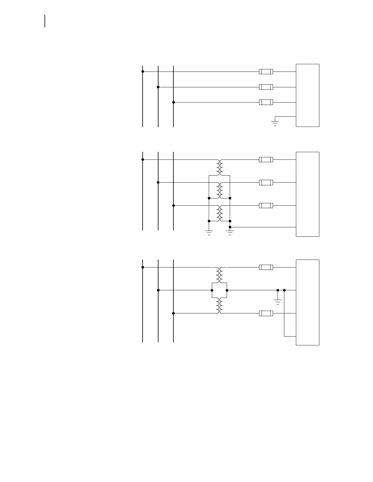
Figure 2.18 Voltage Connections
Note: The VT secondary circuit should be grounded in the relay cabinet.
Note: For open-delta VT connections, the figure shows grounding Phase B (E02). You can
choose to ground Phase A or Phase C instead of Phase B, but the jumper between terminals
E02 and E04 must remain as is.
AB
C
AB
C
SEL-787
EO1
EO2
EO3
EO4
EO1
EO2
EO3
EO4
Direct Connection (Grounded System)
Wye-Wye VT Connection
Open-Delta VT Connection
F1
F2
F3
SEL-787
F1
F3
AB
C
EO1
EO2
EO3
EO4
SEL-787
F1
F2
F3