2.2
SEL-787 Relay Instruction Manual Date Code 20150130
Installation
I/O Configuration
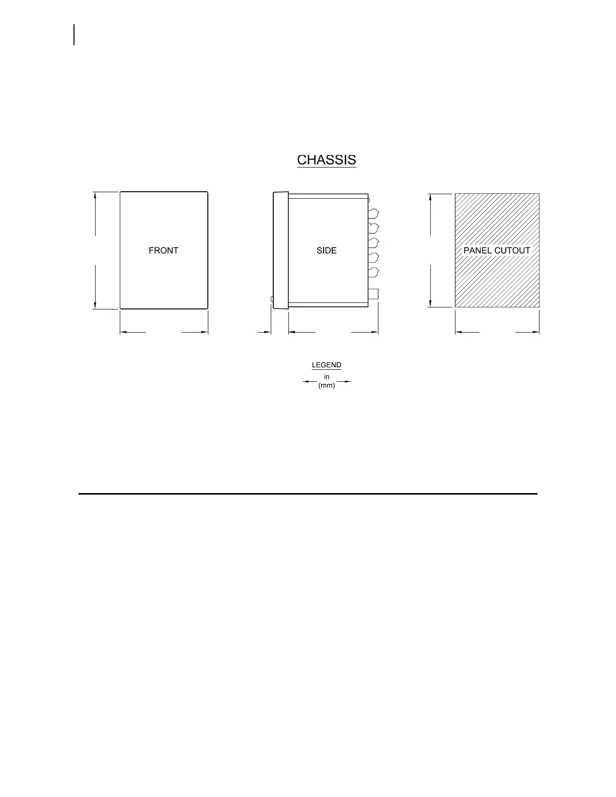
Relay Mounting
To flush mount the SEL-787 in a panel, cut a rectangular hole with the
dimensions shown in Figure 2.1. Use the supplied front-panel gasket for
protection against dust and water ingress into the panel (IP65).
For extremely dusty environments, use the optional IP54-rated terminal dust-
protection assembly (SEL Part #915900170). The 10°C temperature derating
applies to the temperature specifications of the relay.
Figure 2.1 Relay Panel-Mount Dimensions
Refer to Section 1: Introduction and Specifications, Models, Options, and
Accessories for information on mounting accessories.
I/O Configuration
Your SEL-787 offers flexibility in tailoring I/O to your specific application. In
total, the SEL-787 has six rear-panel slots, labeled as Slots A, B, C, D, E, and Z.
Slots A, B, and Z are base unit slots, each associated with a specific function.
Optional digital and analog I/O, communications, RTD, and voltage cards are
available for the SEL-787. Figure 2.2 shows the slot allocations for the cards.
Because installations differ substantially, the SEL-787 offers a variety of card
configurations to provide options for the many diverse applications. Choose
the combination of cards most suited for your application from the following
selection.
5.47
(139.0)
7. 36
(187.0)
5.80
(147.4)
5.67
(144.0)
7.56
(192.0)
1.12
(28.5)
i9089b