2.14
SEL-787 Relay Instruction Manual Date Code 20150130
Installation
I/O Configuration
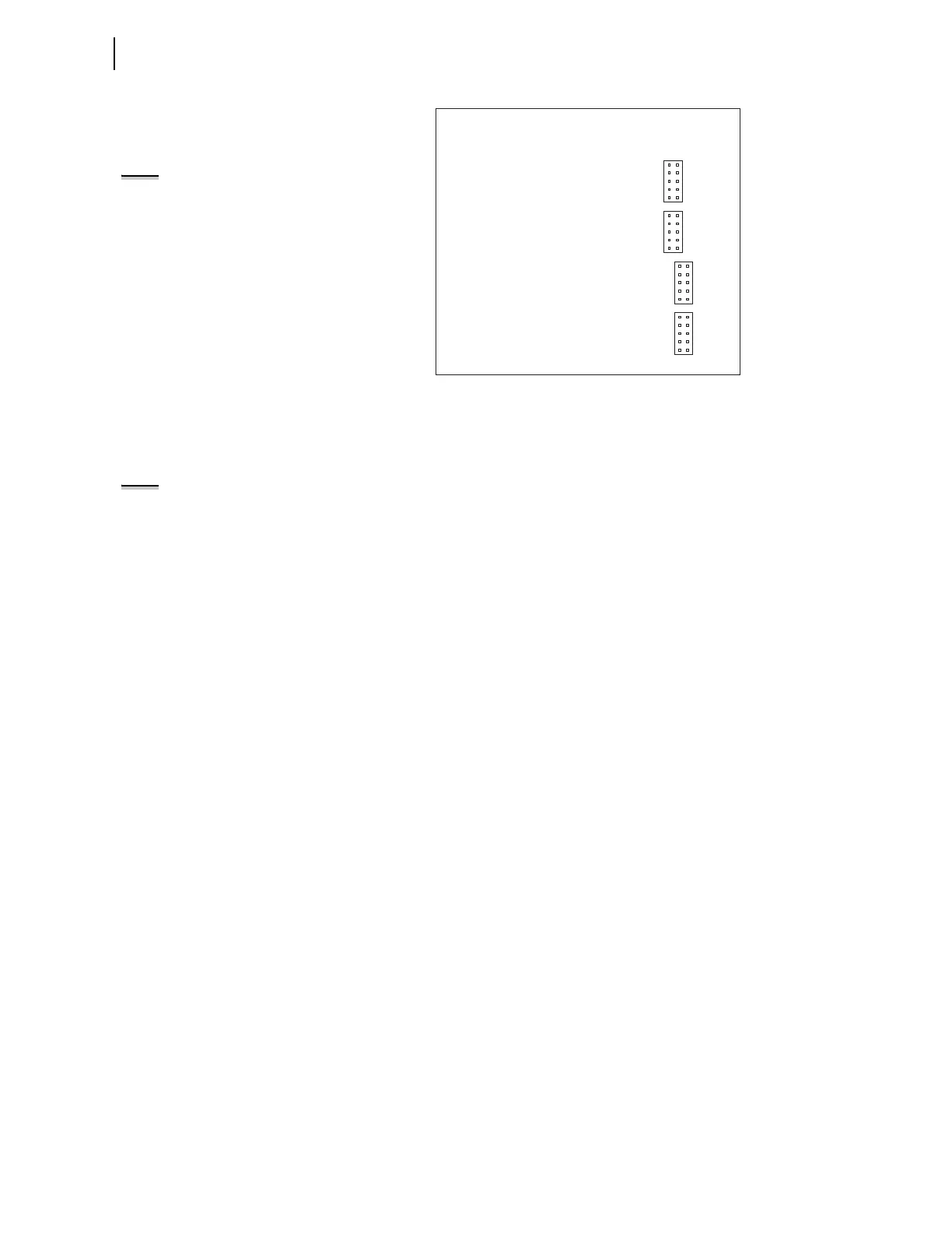
Figure 2.4 JMP1 Through JMP4 Locations on 4 AI/4 AO Board
You need to insert three jumpers for a current analog output selection and two
jumpers for a voltage analog output selection. For a current analog output
selection, insert a jumper between pins 1 and 2, pins 5 and 6, and pins 9 and
10. For a voltage analog output selection, insert a jumper between pins 3 and
4, and pins 7 and 8. Figure 2.5 shows JMP4 selected as a current analog
output. The current analog output selection is the default setting for JMP1
through JMP4. Figure 2.6 shows JMP1 selected as a voltage analog output.
9
7
5
3
1
10
8
6
4
2
JMP1
9
7
5
3
1
10
8
6
4
2
JMP2
9
7
5
3
1
10
8
6
4
2
JMP3
9
7
5
3
1
10
8
6
4
2
JMP4
NOTE: Analog inputs cannot provide
loop power. Each analog output is self-
powered and has an isolated power
supply.
NOTE: There is no jumper between
pins 5 and 6 for a voltage analog
output selection.