2.18
SEL-787 Relay Instruction Manual Date Code 20150130
Installation
Rear-Panel Connections
Rear-Panel Connections
Rear-Panel and Side-
Panel Diagrams
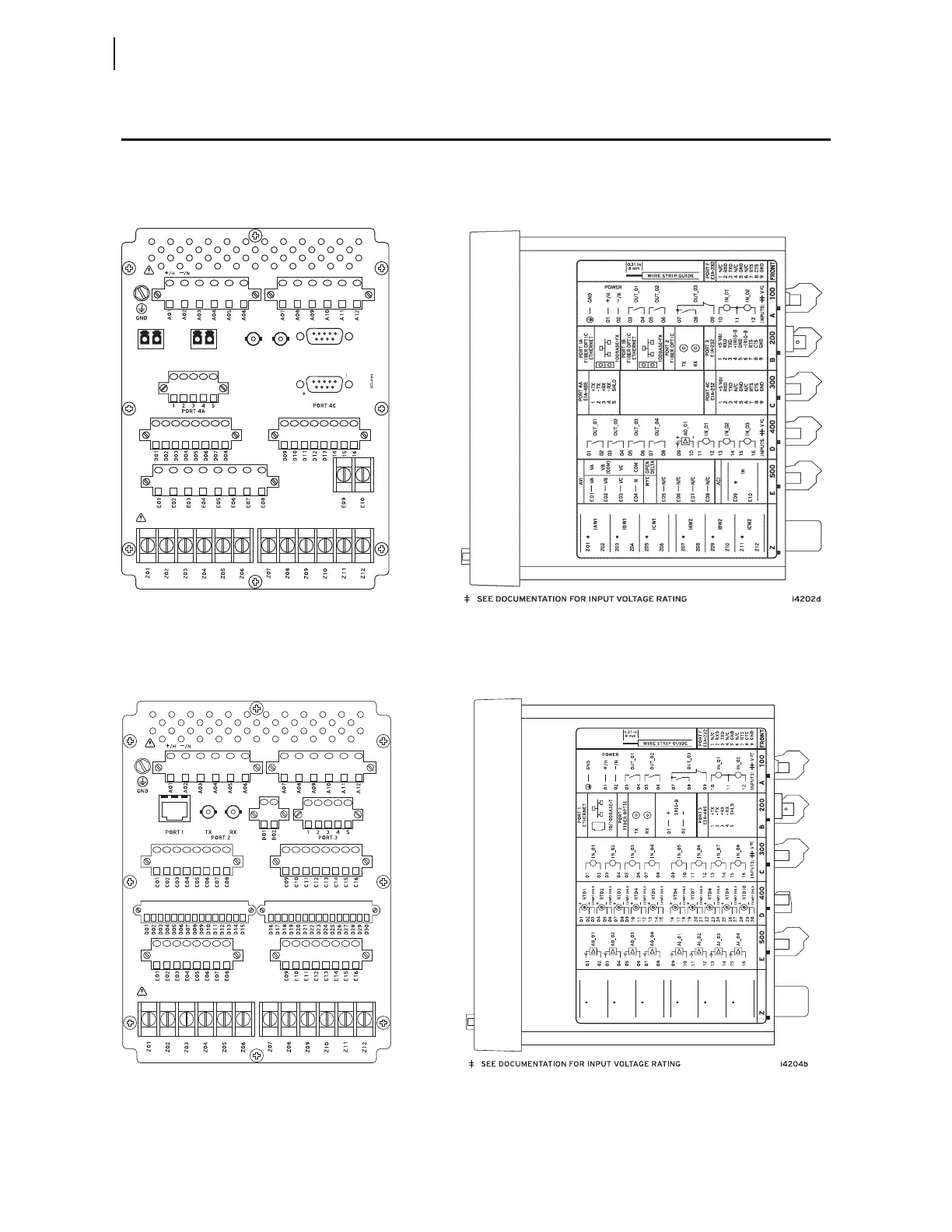
The physical layout of the connectors on the rear-panel and side-panel
diagrams of three sample configurations of the SEL-787 are shown in
Figure 2.9, Figure 2.10, and Figure 2.11.
Figure 2.9 Dual-Fiber, Ethernet, EIA-232 Communication, 3 DI/4 DO/1 AO, and Current/Voltage (1 ACI/3 AVI)
Option
Figure 2.10 Single Copper Ethernet, 8 DI, RTD, and 4 AI/4 AO Option
i4201a
PORT 2
TX RX
1
9
PORT 3PORT 1A PORT 1B
(A) Rear-Panel Layout
(B) Side-Panel Input and Output Designations
Z02
IAW1
Z03
Z04
IBW1
Z05
Z06
ICW1
Z01
Z08
IAW2
Z09
Z10
IBW2
Z11
Z12
ICW2
Z07
(A) Rear-Panel Layout
(B) Side-Panel Input and Output Designations