SEL
ECT
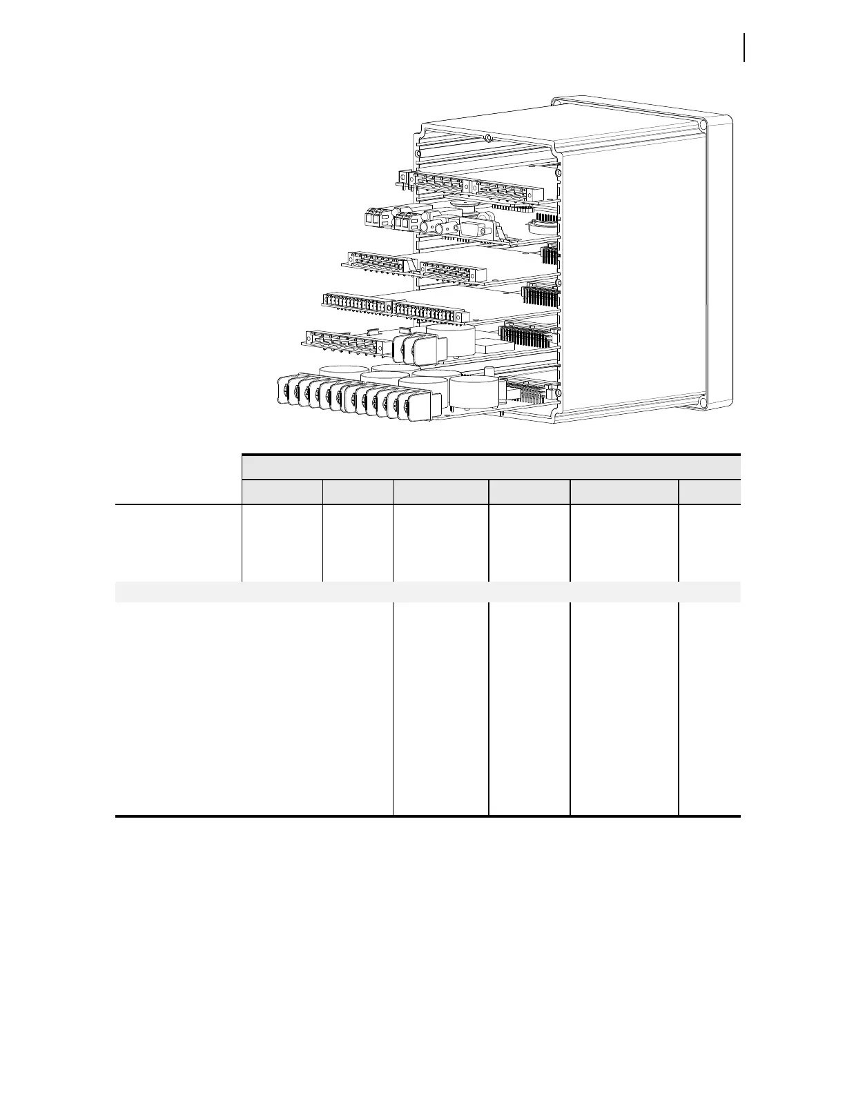
Power Supply With I/O (Slot A)
SEL
ECT
Processor and
Communications Card (Slot B)
SEL
ECT
I/O Expansion Card (Slot C)
SEL
ECT
I/O Expansion Card (Slot D)
SEL
ECT
I/O Expansion Card (Slot E)
SEL
ECT
6 ACI Card (Slot Z)
Rear-Panel Slot
A
B C D E Z
Software Reference
1
(e.g., OUT101)
n/a 3
(e.g., IN301)
4
(e.g., OUT401)
5
(e.g., AI501)
n/a
Description
Power supply
and I/O card
a
a
Power supply, two inputs, and three outputs.
CPU/comm.
card
b
b
IRIG-B, EIA-232/485, fiber-optic serial and/or Ethernet ports.
The IRIG-B input option is available on terminals B01, B02 for all models except models with fiber-optic Ethernet port (P1) and dual copper
Ethernet port (P1). IRIG-B is also supported via fiber-optic serial port (PORT 2) and rear-panel EIA-232 serial port (PORT 3). You can use
only one input at a time.
Comm. or input/
output
c
card
c
Digital or analog.
Input/output
c
or RTD card
Input/output
c
or
voltage/current card
CT card in
base unit
Card Type
SELECT EIA-232/485 l n/a n/a
SEL
ECT DeviceNet l n/a n/a
SEL
ECT 3 DI/4 DO/1 AO (one card per relay) l l l
SEL
ECT 4 DI/4 DO l l l
SEL
ECT 4 DI/3 DO (2 Form C, 1 Form B)
d
ll l
SEL
ECT 8 DI l l l
SEL
ECT 4 AI/4 AO (one card per relay) l l l
SEL
ECT 10 RTD n/a l n/a
SEL
ECT 1 ACI/3 AVI n/a n/a l
SEL
ECT 1 ACI n/a n/a l
d
Available in firmware releases R104 or greater and R203 and greater