2.17
Date Code 20150130 Instruction Manual SEL-787 Relay
Installation
I/O Configuration
Rear-Panel Connections
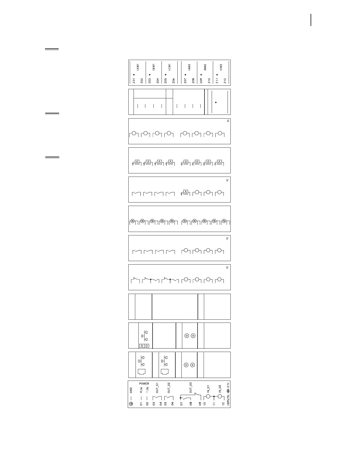
Figure 2.8 shows the rear-panel connections for selected cards. Connections
for additional cards are shown in Figure 2.9 through Figure 2.11.
Figure 2.8 Rear-Panel Connections of Selected Cards
Card 1: Six CT Input Current Card
(6 ACI)
Card 2: Three PT /1 CT Input Card
(1 ACI/3 AVI)
Card 3: Eight Digital Input Card
(8 DI)
Card 4: Four Analog Input/Four Analog
Output Card
(4 AI/4 AO)
Card 5: Three Digital Input/Four Digital
Output/One Analog Output Card (3
DI/4 DO/1 AO)
Card 6: RTD Card (10 RTD)
Card 7: Four Digital Input/Four Digital
Output Card (4 DI/4 DO)
Card 8: Four Digital Input/Three Digital
Output Card
(4 DI/3 DO)
Card 9: Communications Card (EIA-232/
EIA-485)
Card 10: Main Board With Single Fiber-Optic
Ethernet, Fiber-Optic Serial, and
EIA-232 Rear Ports
Card 11: Main Board With Dual Copper
Ethernet, Fiber-Optic Serial, and
EIA-232 Rear Ports
Card 12: Two Digital Input/Three Digital
Output Power Supply Card
(2 DI/3 DO)
NOTE: After any change, be sure to
thoroughly test the settings.
ACI
AVI
E10
IN
E09
WYE
OPEN
DELTA
E05
E06
N/C
N/C
E08
E07
N/C
N/C
E02 VB
VB
(COM)
E03 VC VC
E04 N COM
VA VAE01
INPUTS:
08
05
06
02
04
09
03
10
11
12
13
14
15
16
07
01
IN_01
IN_02
IN_03
IN_04
IN_05
IN_06
IN_07
IN_08
AO_02
AO_0 1
AO_03
AO_04
AI_02
AI_0 1
AI_03
AI_04
08
05
06
02
04
09
03
10
11
12
13
14
15
16
07
01
INPUTS:
AO_0 1
IN_01
IN_02
IN_03
OUT_0 1
OUT_02
OUT_03
OUT_04
08
05
06
02
04
09
03
10
11
12
13
14
15
16
07
01
+
—
08
05
06
04
09
20
21
22
23
24
25
26
27
28
29
30
10
11
12
13
14
15
16
17
18
19
07
02
03
01
RTD 1
COMP/ SHLD
+
—
RTD2
COMP/ SHLD
+
—
RTD3
COMP/ SHLD
+
—
RTD4
COMP/ SHLD
+
—
RTD5
COMP/ SHLD
+
—
RTD6
COMP/ SHLD
+
—
RTD7
COMP/ SHLD
+
—
RTD8
COMP/ SHLD
+
—
RTD9
COMP/ SHLD
+
—
RTD 10
COMP/ SHLD
+
—
INPUTS:
IN_0 1
IN_02
IN_03
IN_04
OUT_0 1
OUT_02
OUT_03
OUT_04
08
05
06
02
04
09
03
10
11
12
13
14
15
16
07
01
INPUTS:
IN_01
IN_02
IN_03
IN_04
OUT_0 1
OUT_02
02
04
05
09
03
OUT_0307
08
06
10
11
12
13
14
15
16
01
PORT 4C
+5 Vdc
RXD
N/C
TXD
GND
5
N/C
RTS
GND
EIA–232
1
2
4
3
6
8
CTS
7
9
+TX
–TX
+RX
–RX
SHLD
5
PORT 4A
EIA–485
1
2
4
3
+5 Vdc
RXD
+IRIG–B
TXD
GND5
–I RIG–B
RTS
GND
PORT 3
EIA–232
PORT 2
FI BER OPTI C
TX
RX
1
2
4
3
6
8
CTS
7
9
PORT 1
ETHERNET
100BASE–FX
FI BER OPTI C
+5 Vdc
RXD
+IRIG–B
TXD
GND5
–I RIG–B
RTS
GND
PORT 3
E IA–232
PORT 2
FI BER OPTI C
TX
RX
1
2
4
3
6
8
CTS
7
9
PORT 1B
ETHERNET
10/100BASE–T
PORT 1A
ETHERNET
10/100BASE–T
NOTE: Analog outputs are isolated
from each other and from the chassis
ground.
NOTE: All digital input and digital
output (including high-current, high-
speed hybrid) connections are polarity
neutral.