3.13
Date Code 20150130 Instruction Manual SEL-787 Relay
PC Software
Meter and Control
the LED. To change the color of the LED, click in the square and make your
selection from the color palette.
The front-panel LEDs display the status of the 16 front-panel LEDs. Use the
front-panel settings to change the front-panel LED assignment.
The Phasors, Fundamental, Min/Max, etc., screens display the
corresponding values.
Click on the Targets button to view the status of all the Relay Word bits.
When a Relay Word bit has a value of 1 (ENABLED = 1), the Relay Word bit
is asserted. Similarly, when a Relay Word bit has a value of 0 (RB02 = 0), the
Relay Word bit is deasserted.
The Status and SER screens display the same information as the ASCII STA
and SER commands.
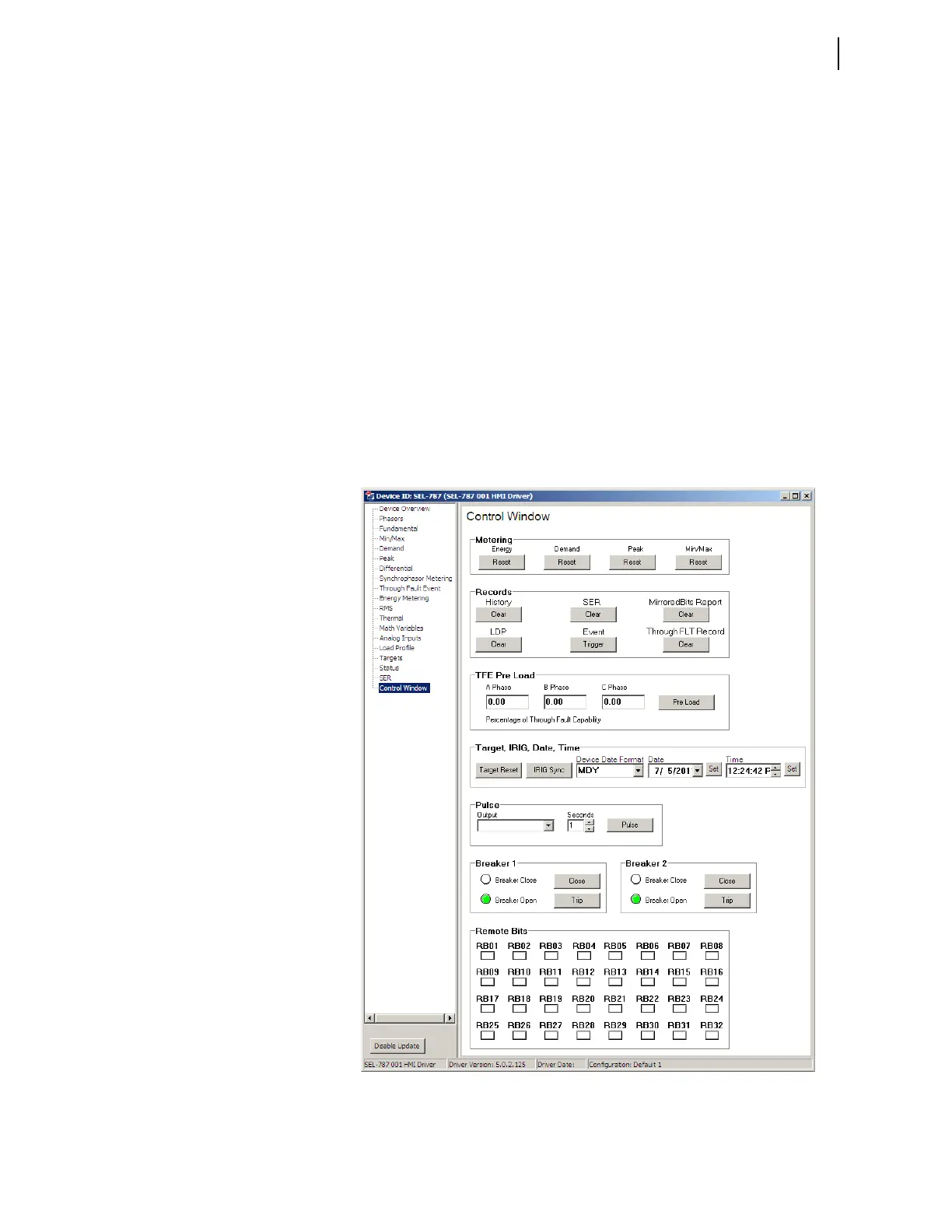
Figure 3.13 shows the control screen. From here you can clear the Event
History, M
IRRORED BITS report, SER, trigger events, and reset metering data.
You can also reset the targets, synchronize with IRIG, and set the time and
date. The Through-Fault Event (TFE) Monitor Pre-load can be entered here
also.
Figure 3.13 Control Screen